Automotive / Garage Equipment
Owner's Manual for Tradequip 2068T Auxiliary Lifter Kit
Quick guide for the Tradequip 2068T Auxiliary Lifter Kit. Includes assembly instructions, safe operating procedures, maintenance tips, and troubleshooting for this 500kg capacity lifter.
Quick answers from the manual
Quick answer
- The Tradequip 2068T is an auxiliary lifter kit with a 500kg capacity, designed for partial temporary support of vehicle components during removal and installation. It is not a standalone transmission lifter. p. 1, 4
Key actions
- Open the breather valve before use. p. 4
- Purge the hydraulic system to remove air. p. 4
First start
- Assemble the unit by attaching legs to the base and fitting the castors. p. 4
- Purge the system before first use. p. 4
Problems and fixes
Unit fails to extend
Check fluid level or purge air.
p. 7Maintenance and reset
- Replace hydraulic oil at least once a year. p. 5
Technical specifications
| Parameter | Value | Meaning | Pages |
|---|---|---|---|
| Rated Capacity | 500kg | Maximum load | p. 1 |
| Working Height | 1175-1985 mm | Operating range | p. 1 |
Where to find it in the PDF
- Assembly and Operation p. 4
- Parts List p. 8, 9
Table of contents
Manual images
Click an image to enlargeQuick guide from the manual
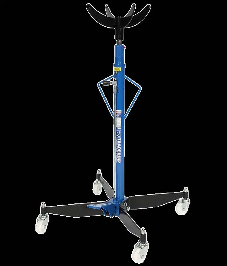
The Tradequip 2068T Auxiliary Lifter Kit is designed for the partial, temporary support of vehicle components during removal and installation. It features a 500kg rated capacity and a working height range of 1175-1985 mm. Important: This unit is not intended as a standalone transmission lifter. Always ensure the breather valve is open before use and purge the hydraulic system to remove air.
Assembly
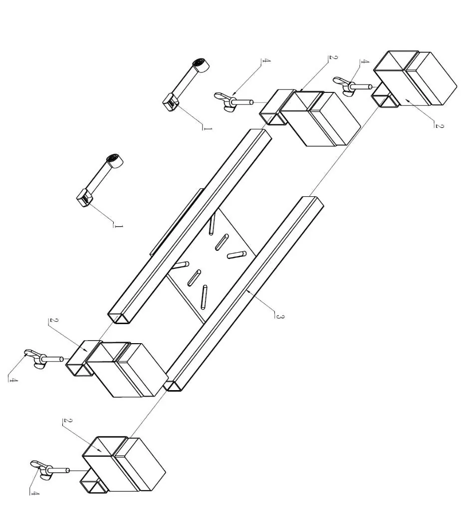
- Attach the two legs to the base using the provided bolts and lock washers.
- Fit the four castors to the legs using the nuts and washers.
- Place the saddle onto the top of the piston rod and slide it down.
Before use
Prior to operation, perform a visual inspection for cracked welds, leaks, or missing parts. Allow the lifter to sit for one hour to let the oil settle. To purge the hydraulic system: loosen the air vent screw, hold the release handle to the right, and pump the foot pedal 15-20 times.
Operation
Roll the lifter into position and pump the foot pedal until the saddle reaches the desired height. Carefully center the load on the saddle, ensuring the center of gravity is stable. To lower the load, slowly and carefully turn the release handle to the right. The speed of descent is controlled by how far the valve is opened.
Maintenance
- Lubrication: Periodically lubricate pivot points, axles, and hinges with light lubricating oil or bearing grease.
- Oil Level: Check the hydraulic oil level by removing the air vent screw with the jack in the lowest position. Add high-quality hydraulic jack oil if necessary.
- Oil Change: Replace the complete hydraulic oil at least once a year. Drain the oil by laying the jack on its side, then refill with approved hydraulic jack oil.
- Cleaning: Keep the piston rod clean and free of rust. Never use sandpaper or abrasive materials on the piston rod.
Troubleshooting
If the unit fails to extend or responds poorly, check the fluid level and ensure the system has been purged of air. If the release handle malfunctions or the cylinder is binding, the unit may require disassembly and cleaning. Always ensure the breather valve is open during operation.
Manufacturer information
TradeQuip
Practical help
Common problems
Unit fails to extend or extends partially
Check fluid level and fill to the correct level as described in the maintenance section.
Incomplete or spongy cylinder response
Check fluid level, purge air from the system, or check pressure.
Unit fails to extend when pedal is pumped
Check for release handle malfunction or contamination; disassemble and clean the unit.
Cylinder doesn't retract or retracts slowly
Check for release handle malfunction or binding; disassemble and clean the unit.
Before use
- Ensure the breather valve is open.
- Conduct a visual inspection for leaks, cracks, or loose parts.
- Allow oil to settle for one hour.
- Purge air from the hydraulic system.
- Test the jack without a load by raising it to full height.
Specs in practice
- Rated Capacity
- The maximum load the lifter can support (500kg).
- Working Height
- The operating range of the lifter (1175-1985 mm).
Images and diagrams
- The manual includes an exploded parts diagram to assist with assembly and maintenance.
- Bracket C is specifically designed for fuel tank removal.
Model compatibility
- Not intended as a standalone transmission lifter.
- Use only for partial temporary support of vehicle components.

Manual page author
David Miller
Documentation analyst
Organizes user manual content into clear summaries, with attention to model details, product context, and everyday usability.