Tools / Tool Storage
User Manual for VEVOR 100HL Outboard Steering System
Quick guide for the VEVOR 100HL Outboard Steering System. Includes installation steps, cable routing, maintenance tips, and safety precautions.
Table of contents
Manual images
Click an image to enlargeQuick guide from the manual
This manual provides essential instructions for the VEVOR 100HL Outboard Steering System. Before operating or servicing, read and understand all instructions to prevent personal injury or property damage. For technical support, visit www.vevor.com/support.
Important safety precautions
- Assemble only according to these instructions.
- Keep the assembly area clean and well-lit.
- Do not assemble when tired or under the influence of alcohol, drugs, or medication.
- Do not substitute parts from other manufacturers; use only VEVOR steering cables.
- Do not attach electrical ground wires to the helm to prevent electrolytic reactions.
- Ensure the outboard motor or outdrive trim tabs are adjusted according to the motor manufacturer's manual to avoid excessive steering loads.
Installation
Helm Assembly:
- Locate the full-size mounting template at the desired location. Drill three 11/32" diameter holes and one 3" diameter center hole.
- Secure the Mounting Bracket (#1 or #8) to the dash using Bolts (#2), Washers (#3), and Lock Nuts (#4). Torque Lock Nuts to 50 lbs·in.
- Insert the Helm through the cutout. Attach it to the Mounting Bracket and secure with Bolts (#5). Torque to 25-30 lbs·in.
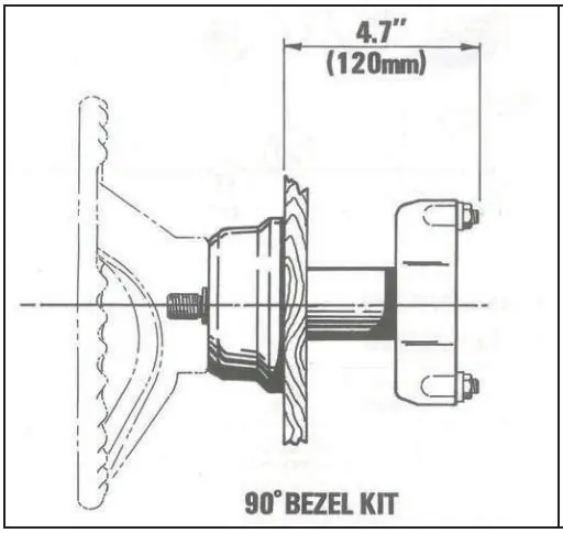
- For 90-degree Bezel Kit: Place Trim Bezel (#7) over the shaft with the "VEVOR" logo pointing upwards and snap it into place.
- Install the Key (#6) into the steering shaft slot, align with the steering wheel keyway, and slide the wheel onto the shaft. Secure with Washer (#10) and Nut (#11), torqued to 25-30 lbs·in.
Steering cable installation
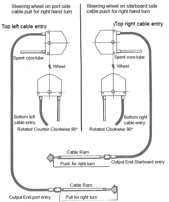
- Clean cable fixing holes and apply marine grease to the cable arm surface. Insert the cable into the mounting hole and tighten the fastening nut at the starboard entry.
- Insert the other end of the cable into the steering rudder. Turn the steering wheel counterclockwise to seat the cable fully. Tighten cable fastening screws.
- Ensure the cable bending radius is not less than R200mm.
- Turn the steering wheel clockwise to adjust the cable end to the proper mounting position (outer engine string in the forward position). Tighten the nut connecting the steering rod to the cable.
Operation and maintenance
Caution: Over-trimming the engine can increase steering torque, making the wheel feel "locked." Reduce boat speed or adjust trim to resolve this.
- Periodically check all fasteners for security and integrity.
- Keep moving parts free from salt and foreign material. Periodically clean the support tube and telescopic end of the cable, then lubricate with waterproof marine grease.
- Inspect for corrosion; replace affected parts immediately.
- Inspect the steering cable for cracks or damage. If found, replace the cable immediately. Do not cover cracks with tape or sealants.
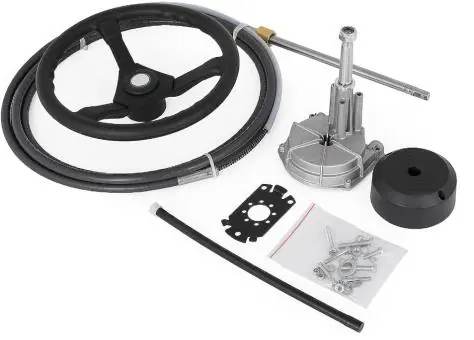
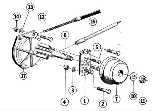
Parts breakdown
Refer to the parts diagram for visual identification of components, including the Bracket (#1), Screws (#2, #5), Key (#6), Trim Bezel (#7), and Helm-Drive Assembly (#17).
Official resources from the manual
Manufacturer information
VEVOR
Practical help
Common problems
Steering feels locked
Engine may be over-trimmed. Reduce boat speed or adjust engine trim out position.
Stiff steering operation
Cable may be dirty or damaged. Clean and lubricate the support tube and cable end; replace if stiff.
Corrosion on parts
Inspect periodically. Replace any corroded parts using original self-locking hardware.
Before use
- Check all fasteners for security and integrity.
- Ensure cable bending radius is not less than R200mm.
- Verify steering wheel turns freely.
- Check for cable cracks or damage.
- Ensure no electrical ground wires are attached to the helm.
Specs in practice
- Bending radius
- Minimum R200mm required to prevent cable damage and premature wear.
- Lock Nut Torque
- 50 lbs·in for mounting bracket nuts.
- Helm Bolt Torque
- 25-30 lbs·in for helm attachment bolts.
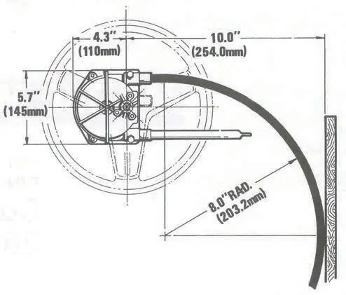
Images and diagrams
- Figure 1/2: Shows mounting dimensions and bezel kit installation.
- Figure 4: Illustrates cable entry and steering direction (push/pull) configuration.
Model compatibility
- Use only VEVOR steering cables.
- Do not substitute parts from other manufacturers.
- Do not change steering from dual cable to single cable system.

Manual page author
David Miller
Documentation analyst
Organizes user manual content into clear summaries, with attention to model details, product context, and everyday usability.