Sports / Marine Controls
Installation Manual for Dometic FT7000P Pro-Pedal Foot Throttle
A comprehensive installation and adjustment guide for the Dometic FT7000P Pro-Pedal Foot Throttle. This manual covers cable routing, mounting procedures, engine control adjustments, and maintenance requirements for marine applications.
Table of contents
Manual images
Click an image to enlargeQuick Guide for Installation
The Dometic Pro-Pedal Foot Throttle is designed for mechanical throttle operation in marine engines. Proper installation is critical for safety and performance. Ensure you have the correct cable length by measuring the routing path and adding 4 feet for a loop. Always disconnect power before beginning installation. The system requires specific cable routing to avoid sharp bends and heat sources.
Safety Information
WARNING: Failure to follow instructions can result in death or serious injury. Always use Dometic-approved replacement parts. Do not modify the product. Ensure the engine is in neutral and turned off before making any adjustments.
Compatibility
This engine control is compatible with engines from the following manufacturers: BRP/OMC, Evinrude/Johnson, Honda, Mercury/MerCruiser, Nissan, Suzuki, Tohatsu, US Marine, Volvo, and Yamaha.
Preinstallation
Before installing, plan the cable routing carefully:
- Avoid areas of excess heat (e.g., exhaust manifolds).
- Avoid sharp edges that cause chafing.
- Maintain the minimum bend radius: 4 in. (10 cm) for Dometic Xtreme cables, 8 in. (20 cm) for standard cables.
- Do not bundle cables with electrical wiring.
- Do not clamp the cable within 36 in. (91 cm) of the engine control.
Installation
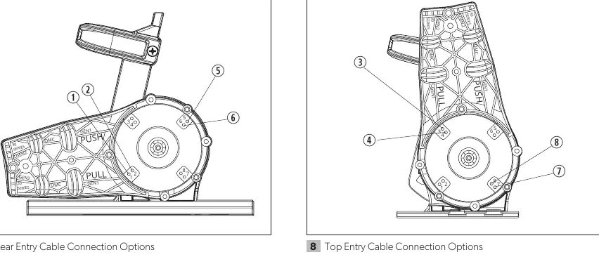
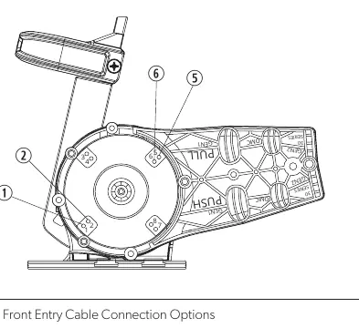
Connecting the Cable: Determine the cable entry direction (rear, top, or front) and select the appropriate throttle wheel number based on your engine manufacturer and whether it is a 'push to open' or 'pull to open' throttle system. Secure the cable bearing and terminal to the throttle wheel as specified in the diagrams.
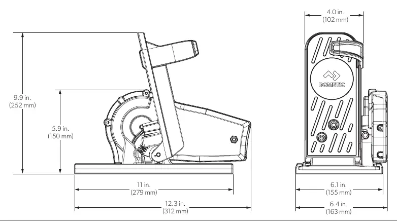
Mounting: The unit can be mounted directly to the deck or using a slide mount. Ensure there is adequate clearance for the full range of pedal movement and for the operator's leg.
Adjusting the Engine Control
Adjustments should be made with the engine off and in neutral:
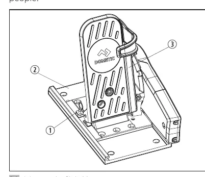
- Slide Mount: Pull the spring-loaded pin to slide the pedal assembly to the desired position.
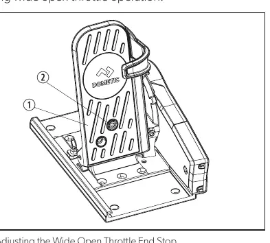
- Wide Open Throttle End Stop: Turn the adjustment screw clockwise to decrease the pedal travel arc.
- Torsion Spring: Turn the adjustment screw counter-clockwise to reduce pressure and soften pedal return.
- Idle Adjustment: Turn the idle adjustment screw clockwise to lower the starting idle position.
Maintenance
Regular maintenance is required to ensure safe operation:
- Periodically check all fasteners for secureness.
- Keep moving parts free from salt and debris.
- Inspect cables for cracks or stiffness; replace if damaged.
- Treat exposed metal components with marine-grade wax.
Manufacturer information
Dometic
Practical help
Common problems
Difficult throttle control or loss of motion
Check for sharp or frequent cable bends; ensure the path adheres to the minimum bend radius requirements.
Hard shifting
Ensure the cable is free of load when the throttle lever is in the idle position.
Control system failure
Inspect for loose fasteners, corrosion, or cracked cables. Replace damaged components immediately.
Before use
- Verify engine compatibility.
- Plan cable routing to avoid heat and sharp edges.
- Measure cable length correctly (add 4 ft for loop).
- Disconnect power before installation.
- Ensure sufficient clearance under the deck.
- Confirm all fasteners are secure.
Specs in practice
- Minimum Bend Radius (Dometic Xtreme)
- 4 in. (10 cm)
- Minimum Bend Radius (Standard)
- 8 in. (20 cm)
- Cable Support Distance
- Do not clamp within 36 in. (91 cm) of the engine control.
Images and diagrams
- Cable Routing: Measure from engine control to engine center, add 4 ft, and round up to the nearest foot.
- Throttle Wheel Selection: Use the provided tables to match your engine manufacturer to the correct throttle wheel number (1-8) based on entry type and sensitivity.
Model compatibility
- Compatible with BRP/OMC, Evinrude/Johnson, Honda, Mercury/MerCruiser, Nissan, Suzuki, Tohatsu, US Marine, Volvo, and Yamaha.

Manual page author
David Miller
Documentation analyst
Organizes user manual content into clear summaries, with attention to model details, product context, and everyday usability.