General / Other Manuals
Viessmann 0-10V OpenTherm Input Module
Installation and configuration guide for the Viessmann 0-10V OpenTherm Input Module. Includes wiring diagrams, operating characteristics, LED status indicators, and troubleshooting steps for compatible Vitodens boilers.
Table of contents
Manual images
Jump to the sectionQuick guide from the manual
This document provides installation and operational instructions for the Viessmann 0-10V OpenTherm Input Module (Part No. 7249 069). This module is designed to accept a 0-10V DC modulating input signal and transmit it to the boiler via OpenTherm communication. Important: Installation, adjustment, and service must be performed by a licensed professional heating contractor. Ensure the main power supply is deactivated and the main gas supply is closed before starting work.
Product Description
The module acts as an interface between a room controller and the boiler. The room controller calculates the heat demand and sends a signal to the boiler, which then adjusts the heat input accordingly. It is compatible with Vitodens 100, WB1A series, WB1B CombiPLUS series, B1HA, and B1KA series boilers.
Operating Characteristics
The boiler target temperature is determined by the DC voltage input:
- Cut-in (Start): The boiler starts when the signal is at least 2.2V.
- Cut-out (Shutdown): The boiler shuts down when the signal falls below 0.9V.
- Modulation: Voltages between 0.9V and 2.2V maintain the supply temperature of 81°F (27°C).
Installation
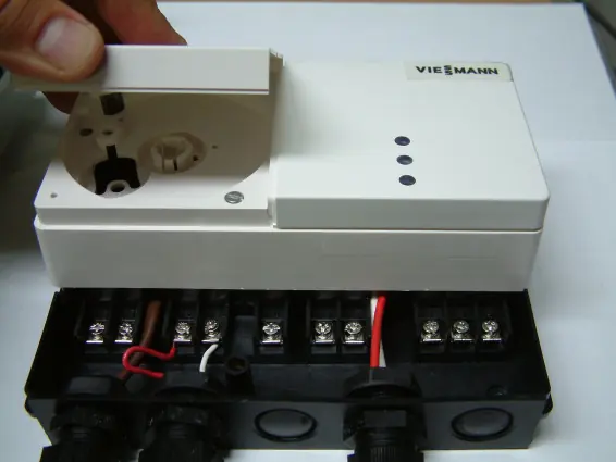
- Remove the left white cover of the Input Module.
- Remove the black cover of the Input Module.
- Loosen the two screws and gently pull the module off its sub-base.
- Remove the required number of knockouts. Install the supplied strain reliefs and guide the wire harness into the terminal box.
- Mount the terminal base onto the wall close to the boiler.
- Make electrical connections as specified in the wiring diagrams.
- Run the Input Module communication cable (2-wire 18AWG) through the Power Pump Module to the boiler control sub-base (Terminals X3.3, X3.4 for WB1A; X21.1, X21.2 for WB1B CombiPLUS; or X21.1, X21.2 for B1HA/B1KA).
- Connect the power supply harness to the RT terminals in the Power Pump Module (Terminals X4.3 and X4.4). Note: B1HA/B1KA series requires an external 24VAC power source (field supplied).
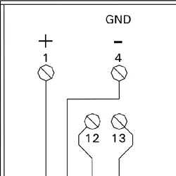
Wiring Diagrams
Refer to the specific wiring diagram for your boiler series (WB1A/WB1B or B1HA/B1KA) provided in the full documentation to ensure correct terminal connections for the 0-10V signal, OpenTherm (OT), 24V power, and fault alarm output.
LED Display Status
The module features three LEDs to indicate status:
- Red: Fault alarm output (dry contact), maximum 1A (Terminals 18-19 closed).
- Yellow: Call for heat.
- Green (flashing): Bus communication established between boiler and Input Module.
Troubleshooting
If a fault occurs, check the display window on the boiler control unit:
- Fault A9 (Red light flashing): Indicates a communication error. Turn the boiler OFF, then ON. Check the communication cable on terminals X3.3, X3.4 or X21.1, X21.2. Verify connections on Input Module terminals 12 and 13. Check the 24VAC output of the Power Pump Module. Ensure the 0-10V input signal is at least 3.0V to start the boiler.
Manufacturer information
Viessmann Climate Solutions
Practical help
Common problems
Fault code A9 (Red light flashing)
This indicates a communication error. Power cycle the boiler, check the communication cable, verify connections on terminals 12/13, and ensure the 0-10V input signal is at least 3.0V.
Boiler not starting
Ensure the DC voltage input signal is above the 2.2V cut-in threshold.
Before use
- Verify boiler compatibility (Vitodens 100, WB1A, WB1B CombiPLUS, B1HA, B1KA).
- Ensure installation is performed by a licensed professional.
- Deactivate main power supply to the equipment.
- Close main gas supply.
- Ensure 24VAC power source is available (required for B1HA/B1KA series).
Images and diagrams
- Wiring diagrams are provided for two groups: WB1A/WB1B series and B1HA/B1KA series.
- Terminals 12 and 13 are used for OpenTherm communication.
- Terminals 18 and 19 are used for the fault alarm output.
Model compatibility
- Compatible with Vitodens 100, WB1A series, WB1B CombiPLUS series, B1HA, and B1KA series boilers.
- B1HA/B1KA series requires an external 24VAC power source (field supplied).

Manual page author
David Miller
Documentation analyst
Organizes user manual content into clear summaries, with attention to model details, product context, and everyday usability.