Hvac / Heat Pumps
Technical Data Manual for Viessmann VITOCAL IND-H Ductless Split System
Technical data and installation guide for Viessmann VITOCAL IND-H ductless split systems. Includes specifications, wiring diagrams, clearance requirements, and compatibility details for models 06XAK through 36XAK.
Table of contents
Manual images
Jump to the sectionQuick Guide from the Manual
This document serves as a technical data manual for the Viessmann VITOCAL IND-H (DLFSHCH Series) ductless split system. It provides essential information for installers and technicians, including model nomenclature, installation clearances, wiring diagrams, and system specifications. Users should refer to this manual to verify electrical requirements, unit dimensions, and compatibility before installation or service.
Product Overview
The VITOCAL IND-H series consists of high-wall indoor units designed for ductless split systems. Key features include:
- Low Sound Levels: Whisper-quiet indoor operation with no indoor compressors.
- Secure Operation: Units connect via refrigerant piping and wiring, preventing ductwork-related security issues.
- Easy Maintenance: Features a removable blower assembly, hood-style cover, and cleanable filters.
- Advanced Controls: Microprocessor-based controls with wireless remote, optional wired controller, and optional Wi-Fi kit.
Installation and Clearances
Proper installation is critical for system performance. Follow these guidelines:
- Unit Leveling: Units must be level in all planes for reliable operation.
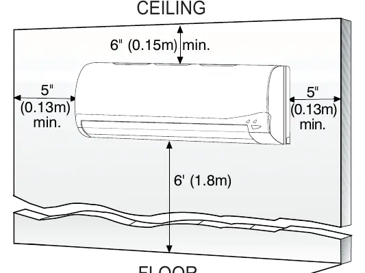
- Clearances: Maintain a minimum of 6 inches (0.15m) of clearance above the unit for proper return airflow. Side clearances should be at least 5 inches (0.13m).
- Location: Position the unit as high as possible on the wall for optimal air circulation. Avoid obstructions like curtains or furniture that may cause short cycling.
- Drainage: High wall fan coil units have internal condensate traps. If gravity drainage is insufficient, use an accessory condensate pump.
Wiring and Electrical Connections
All wiring must comply with NEC (National Electrical Code) or CEC (Canadian Electrical Code) and local regulations.
- Power Supply: The main power is supplied to the outdoor unit. The indoor unit is powered from the outdoor unit.
- Wiring Requirements: Use stranded copper conductors with a 600-volt insulation rating.
- Polarity: Wiring between the indoor and outdoor unit is polarity sensitive.
- Shielded Wire: In high Electromagnetic field (EMF) areas, use 14/2 stranded shielded wire for communication lines if issues arise.
Maintenance and Service
The system is designed for simplified maintenance:
- Coil Cleaning: The draw-thru design of the outdoor section allows for quick cleaning of coils from the inside using a pressure hose and detergent.
- Filters: Equipped with easy-to-use, cleanable filters.
- Diagnostics: The system includes extensive self-diagnostics to assist in troubleshooting.
Technical Specifications
Specifications vary by model (06XAK through 36XAK). Refer to the detailed tables in the manual for:
- Electrical Data: Voltage, phase, and cycle requirements.
- Airflow Data: CFM ratings for Turbo, High, Medium, and Low speeds.
- Sound Pressure: dB(A) ratings for different operation modes.
- Operating Range: Temperature limits for cooling and heating modes.
Manufacturer information
Viessmann Climate Solutions
Practical help
Common problems
Unit performance degradation
Check if top clearance is less than 5.9 inches (15cm), which may reduce airflow and performance.
Communication errors in high EMF areas
Replace standard wiring with 14/2 stranded shielded wire between outdoor and indoor units, landing the shield on the ground in the outdoor unit only.
Condensate drainage issues
If gravity drainage is not possible, install an accessory condensate pump. Ensure the pump lift capacity matches the unit size requirements.
Loose wiring connections
Ensure all wires are connected firmly; loose wiring can cause terminal overheating, malfunction, or fire hazards.
Before use
- Verify the model number and voltage requirements (115V or 208/230V) match your power supply.
- Ensure the mounting location provides at least 6 inches of top clearance and 5 inches of side clearance.
- Confirm the outdoor unit is compatible with the indoor unit model.
- Check that all wiring is sized according to NEC/CEC and local codes.
- Ensure the unit is level in all planes.
- Verify that no wires are touching refrigerant tubing, the compressor, or moving parts.
Specs in practice
- Nominal Capacity
- Rated cooling/heating capacity in tons (e.g., 06 = 1/2 Ton, 36 = 3 Tons).
- Sound Pressure (dB(A))
- Noise level generated by the unit during operation; lower values indicate quieter operation.
Images and diagrams
- Fig 2: Illustrates the required clearances (6 inches top, 5 inches sides) for proper airflow.
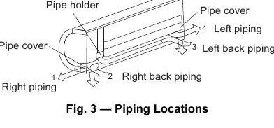
- Fig 3: Shows the various piping routing options (left, right, back) for the indoor unit.
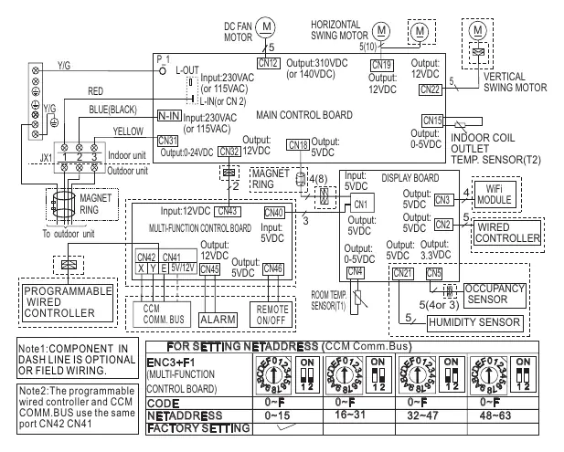
- Fig 5: Wiring diagram for 6K-36K units showing internal connections and control board layout.
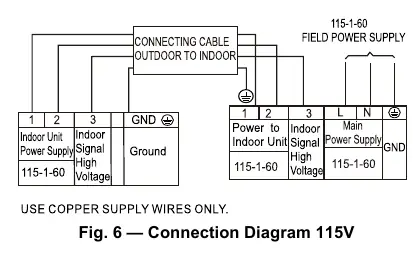
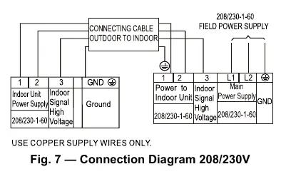
- Fig 6 & 7: Connection diagrams for 115V and 208/230V systems respectively, showing power and communication wiring.
Model compatibility
- Indoor units are matched with specific outdoor single-zone or multi-zone units.
- Refer to the 'Compatibility' table on page 6 to ensure the indoor model matches the intended outdoor unit.

Manual page author
Emily Carter
User documentation editor
Prepares concise manual descriptions and highlights the most useful setup, operation, and maintenance information for readers.