HVAC / Parts & Accessories
Installation Instructions for Viessmann Vitodens 200-W Flue Gas Cascade
Professional installation guide for the Viessmann Vitodens 200-W flue gas cascade system. This manual covers safety requirements, component assembly, flue pipe installation in shafts, and configuration for multi-boiler setups.
Quick answers from the manual
Quick answer
- This manual provides installation instructions for the Viessmann Vitodens 200-W flue gas cascade system, which allows for the connection of up to 4 boilers to a common flue. p. 1
Key actions
- Trim flue gas non-return devices at the markings to achieve the required 3° fall. p. 4, 6
- Install a flue gas non-return device above each boiler. p. 1
Technical specifications
| Parameter | Value | Meaning | Pages |
|---|---|---|---|
| Max boilers | 4 | Maximum number of boilers in a common flue cascade. | p. 1 |
| Flue header incline | min. 3° | Minimum upward incline towards the boiler. | p. 1, 4 |
Where to find it in the PDF
- Safety and Installation Info p. 1, 2
- Components p. 3
- Installation Procedures p. 4, 5, 6, 7
Table of contents
Manual images
Click an image to enlargeQuick guide from the manual
This document provides installation instructions for the flue gas cascade system designed for Vitodens 200-W boilers. It is intended for use by competent heating engineers and installation contractors. The system supports up to 4 boilers connected to a common flue.
Safety instructions
Installation, start-up, inspection, maintenance, and repairs must only be carried out by a competent person. Before working on the system:
- Isolate the power supply (e.g., remove a separate mains fuse or use a mains isolator) and safeguard against unauthorized reconnection.
- When using gas as fuel, close the main gas shut-off valve and safeguard against unauthorized reopening.
- Use only original spare parts supplied or approved by Viessmann.
Installation information
Key requirements for the flue gas cascade system:
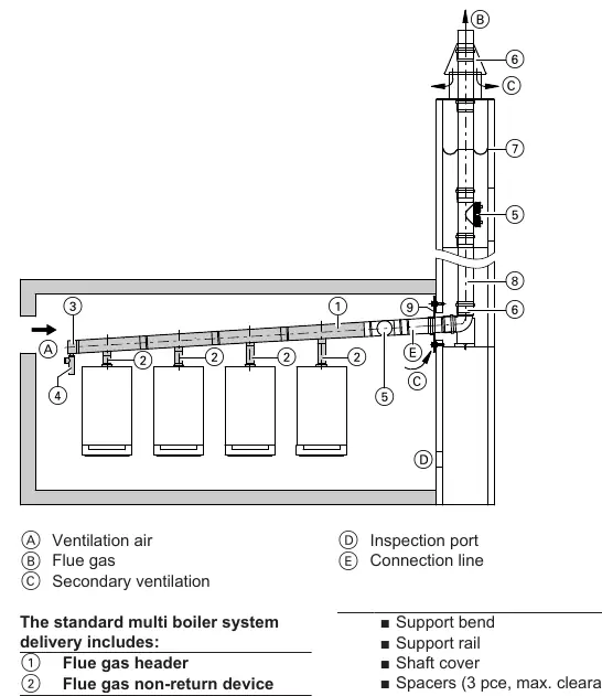
- Capacity: Up to 4 boilers can be connected to a common flue.
- Operation: Flue system in open flue operation with positive pressure.
- Incline: Connect the flue gas header to the chimney with a slight upward incline of at least 3° (approx. 50 mm/m).
- Non-return device: Install a flue gas non-return device above each boiler in the area of the connection to the header.
- Alignment: Align the connection between the flue gas non-return device and the flue gas header horizontally or with a slight fall to the flue gas header.
Combustion air and inspection
Gas equipment with a total rated heating output exceeding 50 kW must be provided with combustion air apertures leading to the outside. The cross-section should be at least 150 cm² and must be 2 cm² larger for each additional kW above 50 kW. An inspection port must be installed inside the installation room as per local regulations (e.g., FeuVo in Germany).
Installation procedures
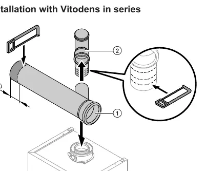
Trimming and mounting
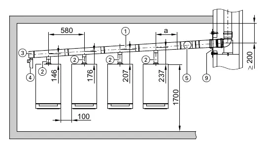
The fall of the flue gas header is achieved by trimming the flue gas non-return devices at the markings. Ensure the flue gas non-return devices are trimmed according to the number of boilers and the clearance between them (standard clearance is 100 mm). Headers should be fitted simultaneously to all flue gas non-return devices.
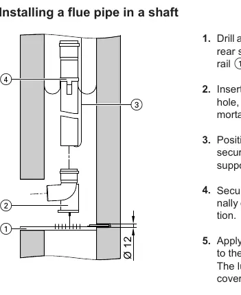
Installing a flue pipe in a shaft
- Drill a 12 mm hole centrally in the rear shaft wall to secure the support rail.
- Insert the support rail and secure it to the front shaft wall.
- Position the support bend and secure it with the pin in the support rail.
- Apply lubricating paste to pipe gaskets.
- Install a spacer every 2 to 5 m, depending on shaft size.
- Push pipes into each other while turning, and lower them into the shaft using an installation rope.
- Secure the flashing and vent bezel at the top of the shaft.
Manufacturer information
Viessmann Climate Solutions
Practical help
Common problems
Incorrect flue header incline
Ensure a minimum upward incline of 3° (approx. 50 mm/m) towards the boiler.
Improper non-return device fit
Trim the flue gas non-return devices at the specific markings based on the number of boilers and clearance.
Before use
- Ensure the installer is a competent heating engineer.
- Isolate the power supply to the heating system.
- Close the main gas shut-off valve.
- Verify the number of boilers (max 4).
- Check that the flue gas header has a minimum 3° incline.
Specs in practice
- Flue header incline
- Minimum 3° (approx. 50 mm/m) upward incline towards the boiler.
- Combustion air aperture
- Required for systems >50 kW; minimum 150 cm² plus 2 cm² per additional kW.
Images and diagrams
- The components diagram identifies the flue gas header, non-return devices, condensate drain, and inspection pieces.
- Installation diagrams show the required dimensions and positioning for series and block configurations.
Model compatibility
- Designed for Vitodens 200-W boilers.
- Supports up to 4 boilers in a cascade.

Manual page author
Michael Turner
Technical manual editor
Reviews PDF manuals for structure, safety notes, and practical product details so readers can find the right information quickly.