HVAC / Air Conditioners
Installation Manual for Viessmann Vitopend 200-W
Professional installation guide for the Viessmann Vitopend 200-W (Type WH2B) gas boiler. Includes detailed mounting instructions, gas and water connection specifications, electrical wiring diagrams, and safety requirements for authorized...
Quick answers from the manual
Quick answer
- This document is the installation manual for the Viessmann Vitopend 200-W (Type WH2B) gas boiler, intended for authorized professionals. It covers mounting, gas/water connections, and electrical wiring. p. 1, 3
Key actions
- Mounting the boiler p. 8
- Electrical wiring p. 14
Problems and fixes
Gas leak detection
Use approved agents (EN 14291); avoid nitrites/sulfides.
p. 12Technical specifications
| Parameter | Value | Meaning | Pages |
|---|---|---|---|
| Power Output | 10.5 to 18 kW or 10.5 to 24 kW | Heating capacity range. | p. 1 |
| Protection Class | IP X4 D | Ingress protection rating. | p. 6 |
Where to find it in the PDF
- Safety Instructions p. 3
- Installation Preparation p. 6
- Electrical Connections p. 14
Table of contents
Manual images
Click an image to enlargeImportant Information for Professionals
This manual is intended exclusively for authorized professionals. All work on gas installations must be performed by installers authorized by the local gas utility company. Electrical work must be performed by qualified electricians. Ensure the system is disconnected from the power supply and secured against reconnection before starting any work.
Installation Preparation
Before mounting the boiler, ensure the following preparations are made:


- Flush the heating system thoroughly.
- Prepare gas connections according to local regulations (TRGI/TRF).
- Prepare electrical connections: Use NYM-J 3 x 1.5 mm² cable with a maximum 16 A fuse (230 V~, 50 Hz).
- Ensure all connections are free of load and torque.
Mounting the Boiler
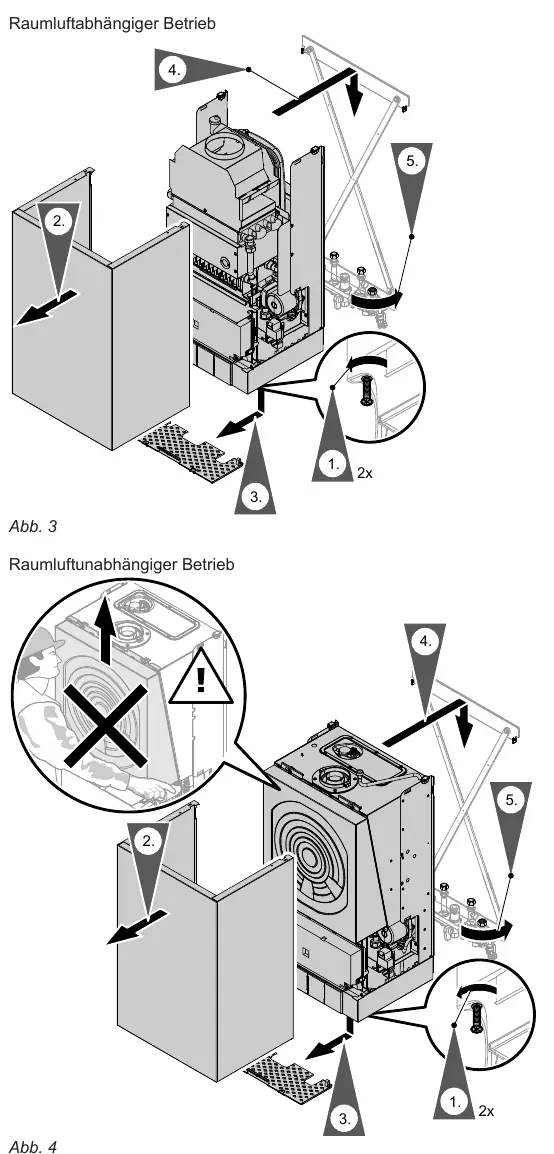
The boiler can be installed for room-sealed or room-independent operation. Follow the specific mounting sequence provided in the diagrams for your chosen operation mode. Ensure the boiler is mounted securely to the wall using the provided mounting frame or template.
Flue Gas Connection
Ensure the flue gas system is gas-tight and that there is a free passage for exhaust gases. Openings for combustion air supply must remain open and cannot be sealed. If operating in room-dependent mode, ensure the cross-section of the flue pipes matches the boiler's connection piece.
Gas Connection
Install the gas shut-off valve. If converting to a different gas type (e.g., LPG), use the appropriate conversion kit. Perform a leak test using approved agents (EN 14291). Do not use leak detection agents containing nitrites or sulfides, as these can cause material damage. The maximum test pressure is 150 mbar; disconnect the boiler from the main line if higher pressure is required.
Electrical Connections
Connect the power supply and accessories according to the wiring diagrams. When connecting accessories, ensure the correct wiring to the control unit. If the boiler is installed in wet rooms, ensure the power supply for accessories is not connected directly to the control unit if it falls outside the wet room protection zone. Always touch a grounded object (e.g., heating pipe) before handling electronic components to prevent damage from electrostatic discharge.
Commissioning
After installation, refer to the separate Service Manual for the Vitopend for detailed commissioning and adjustment procedures.
Manufacturer information
Viessmann Climate Solutions
Practical help
Common problems
Gas leak during testing
Use only approved leak detection agents (EN 14291). Avoid agents with nitrites or sulfides. Remove residue after testing.
Electrostatic discharge damage
Touch a grounded object, such as a heating or water pipe, before touching electronic components to discharge static electricity.
Overpressure during leak test
Do not exceed 150 mbar. If higher pressure is needed, disconnect the boiler and gas fittings from the main line.
Before use
- Ensure the system is disconnected from the power supply.
- Secure the system against accidental reconnection.
- Close the gas shut-off valve and secure it.
- Flush the heating system.
- Verify that the flue gas system is gas-tight.
Specs in practice
- Power Supply
- 230 V~, 50 Hz, max 16 A fuse.
- Protection Class
- IP X4 D (suitable for wet rooms if protected from water jets).
Images and diagrams
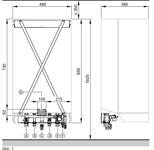
- Abb. 1: Boiler dimensions and connection points (A-G).
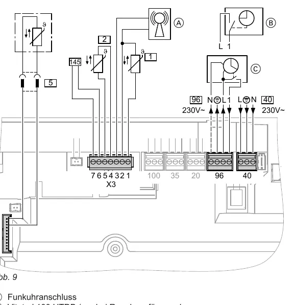
- Abb. 9: Electrical wiring diagram for power and accessories.
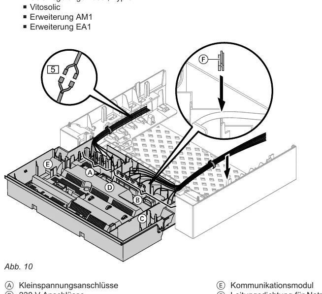
- Abb. 10: Internal electrical connection layout.
Model compatibility
- Only for authorized professionals.
- Requires specific conversion kit for LPG or Natural Gas LL.
- Accessories like Vitotrol 100 require specific wiring and bridge removal.

Manual page author
Emily Carter
User documentation editor
Prepares concise manual descriptions and highlights the most useful setup, operation, and maintenance information for readers.