Power / Solar Panels
User Manual for Xantrex Prosine 1000/1800 Sine Wave Inverter
Quick guide for the Xantrex Prosine 1000/1800 Sine Wave Inverter. Includes installation, wiring, operation, troubleshooting, and battery sizing instructions.
Table of contents
Manual images
Click an image to enlargeQuick Guide from the Manual
The Xantrex Prosine Sine Wave Inverter is designed to provide high-quality, true sine wave AC power from a battery source. This manual provides essential information for the safe installation, operation, and maintenance of the 1000W and 1800W models.
Safety Precautions
Warning: Before installing or using the inverter, read all safety instructions. Do not disassemble the unit; service should only be performed by qualified personnel. Ensure the inverter is not installed in zero-clearance compartments or areas containing flammable materials like gasoline.
Installation
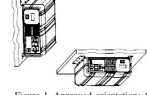
The inverter must be installed in a dry, cool, and well-ventilated location. Maintain at least 5 inches (13 cm) of clearance around the unit. It can be mounted on horizontal or vertical surfaces using the provided mounting holes.
Wiring
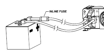
- DC Wiring: Use cables of the correct gauge and keep them as short as possible (ideally 3-6 ft). An inline fuse is required on the positive DC cable, as close to the battery as possible.
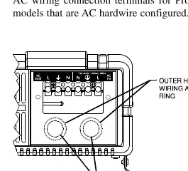
- AC Wiring: For hardwire versions, ensure the AC input and output are protected by appropriate circuit breakers or fuses.
- Grounding: Connect the chassis ground lug to your DC ground system as required by local regulations.
Operation
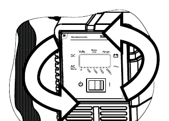
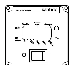
The control panel allows you to monitor battery voltage, input current, and output power. The inverter features a POWERSAVE mode, which reduces standby power consumption by shutting off control circuitry when no load is detected. This mode is factory-set to OFF.
Troubleshooting
If a fault occurs, the control panel will display the error, sound an alarm, and the LCD backlight will blink. Common issues include:
- High/Low Battery Shutdown: Check battery connections, cable size, and charging system.
- Overload Shutdown: Reduce the load on the inverter.
- Overtemp Shutdown: Improve ventilation and cooling.
Technical Specifications
The Prosine Inverter operates on 12V or 24V DC input, converting it to 120V or 230V AC output depending on the model. It features automatic overload, short-circuit, and over-temperature protection.
Practical help
Common problems
No output voltage
Ensure the inverter is switched to (I), check battery connections, and verify the battery fuse is intact.
Low input voltage warning/shutdown
Check for poor DC wiring, undersized cables, or poor battery condition. Recharge the battery.
Overload shutdown
Reduce the load connected to the inverter.
High input voltage shutdown
Check the battery charging system for faults.
Before use
- Ensure battery connections are solid and clean.
- Verify DC cables are of the correct gauge and length (keep as short as possible).
- Ensure the inverter is mounted in a cool, dry, and well-ventilated location.
- Verify all wiring complies with local electrical codes.
- Ensure an appropriate inline fuse is installed on the positive DC line.
Specs in practice
- Continuous Output Power
- The power the inverter can deliver continuously (1000W or 1800W models).
- Surge Rating
- Peak power capacity for starting hard-to-start AC loads (e.g., motors).
- Input Voltage Range
- Operating voltage: 10-16V DC for 12V models, 20-32V DC for 24V models.
- POWERSAVE Mode
- A sleep mode that reduces standby power consumption when no load is detected.
Images and diagrams
- Figure 1: Approved orientations for inverter mounting.
- Figure 2: Control panel attachment and remote mounting.
- Figure 3: AC wiring terminals for hardwire versions.
- Figure 4: Battery connections including inline fuse placement.
Model compatibility
- Designed for use with deep-cycle lead-acid batteries.
- Not for use in compartments containing flammable liquids or gasoline.
- Hardwire versions must be installed by a certified technician.

Manual page author
Michael Turner
Technical manual editor
Reviews PDF manuals for structure, safety notes, and practical product details so readers can find the right information quickly.