Power / Power Inverters
Installation Guide for Xantrex 100W and 160W Solar Panels
A comprehensive installation and maintenance guide for Xantrex 100W and 160W solar panels. Includes wiring diagrams for series and parallel configurations, mounting instructions, and troubleshooting tips.
Table of contents
Manual images
Click an image to enlargeQuick Guide from the Manual
This document provides installation and maintenance instructions for Xantrex 100W (780-0100) and 160W (780-0160) solar panels. Key takeaways include:
- Safety First: Do not ground PV conductors. Do not install on residential structures. All wiring must be performed by a certified technician.
- Mounting: Use the provided Z-brackets. Ensure the roof surface is firm and rigid. Seal all mounting holes with outdoor-rated, waterproof sealant.
- Wiring: Panels can be configured in series, parallel, or a combination. Always check polarity before making final DC connections.
- Maintenance: Perform monthly visual inspections. Clean panels with a soft cloth, water, and mild detergent; avoid abrasive materials and pressure washing.
Safety Information
Read all instructions before installation. The system involves electrical hazards; disconnect all power sources and disable disconnect devices before working. Use insulated tools and remove personal metal items (rings, watches) to prevent short circuits. If the system is damaged, do not operate it.
Basic Installation Steps
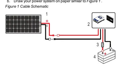
1. Planning: Draw your power system schematic. Identify cable entry points on your vehicle (factory-installed vents or roof entry points). Select a location for the charge controller that is accessible, viewable, and moisture-free.

2. Mounting:
- Prepare the surface by removing dust and debris.
- Install mounting brackets on the panel (Torque: 20 lb-in / 2.3 N-m).
- Mark hole locations on the roof, pre-drill, and apply waterproof sealant.
- Fasten the assembly to the roof using #10 screws (Torque: depends on roof material).
- Apply sealant to screw heads.
3. Connecting DC Cables:
- Cover the panel with a blanket to de-energize it.
- Connect PV cables to the panel using MC4-type connectors.
- Route cables through the roof entry point to the charge controller.
- Connect battery cables to the charge controller and then to the battery terminals (Torque: 10.6 lb-in / 1.2 N-m).
- Secure all cables with clamps or ties.
Solar Panel Wiring
The system supports different configurations depending on your power needs:

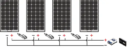
- Series: Connect the positive (+) of the first panel to the negative (-) of the next. Optimized for MPPT chargers.
- Parallel: Connect positive to positive and negative to negative using branch connectors. Optimized for MPPT or PWM chargers.
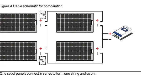
- Combination: Connect panels in series to form strings, then connect strings in parallel. Optimized for MPPT chargers.
Maintenance and Care
Perform monthly visual inspections to check for broken glass, sharp objects, corrosion, or shading. Clean panels in the early morning or evening when cool. Use a soft cloth with water and mild detergent. Do not use chemicals, abrasive materials, or pressure washers.
Troubleshooting
If the battery does not charge:
- Check for shading or insufficient sunlight.
- Verify DC cable connections are tight.
- Check for a blown fuse; replace with a 30A/32V green ATC blade fuse if necessary.
Specifications
100W Solar Panel (780-0100): 19.2V Max Power Voltage, 5.21A Max Power Current, 600VDC Max System Voltage.
160W Solar Panel (780-0160): 19.2V Max Power Voltage, 8.34A Max Power Current, 600VDC Max System Voltage.
Practical help
Common problems
Battery does not charge even in sunlight
Check for shading on the panel, ensure DC cables are securely connected, and inspect the in-line fuse for damage.
Blown fuse
Replace the in-line fuse on the 10AWG positive battery cable with a 30A/32V green ATC blade fuse.
Before use
- Plan the power system layout on paper.
- Gather required tools: #2 Phillips screwdriver, drill, wrench set, torque driver.
- Identify vehicle roof cable entry points.
- Ensure the mounting surface is firm, thick, and rigid.
- Verify all safety and electrical codes are met.
Specs in practice
- Maximum power at STC
- The power output of the panel under Standard Test Conditions (1000W/m2 irradiance, 25°C cell temp).
- Open circuit voltage
- The voltage of the panel when no load is connected.
- Short circuit current
- The maximum current the panel can produce when terminals are shorted.
Images and diagrams
- Figure 1: Basic cable schematic showing the connection path from solar panel to charge controller and battery.
- Figure 2: Series wiring diagram for connecting multiple panels.
- Figure 3: Parallel wiring diagram using branch connectors.
- Figure 4: Combination wiring diagram for series-parallel configurations.
Model compatibility
- Compatible with PWM 30A Charger (PN: 709-3024-01).
- Compatible with MPPT 30A Charger (PN: 710-3024-01).
- Compatible with MPPT Remote Display (PN: 710-0010).

Manual page author
Michael Turner
Technical manual editor
Reviews PDF manuals for structure, safety notes, and practical product details so readers can find the right information quickly.