Garden / Lawn Care
XPOtool Dethatcher Lawn Comb 51704
Quick guide for the XPOtool Dethatcher Lawn Comb 51704. Includes assembly instructions, safety precautions, and a parts list for proper setup and operation.
Table of contents
Manual images
Click an image to enlargeQuick guide from the manual
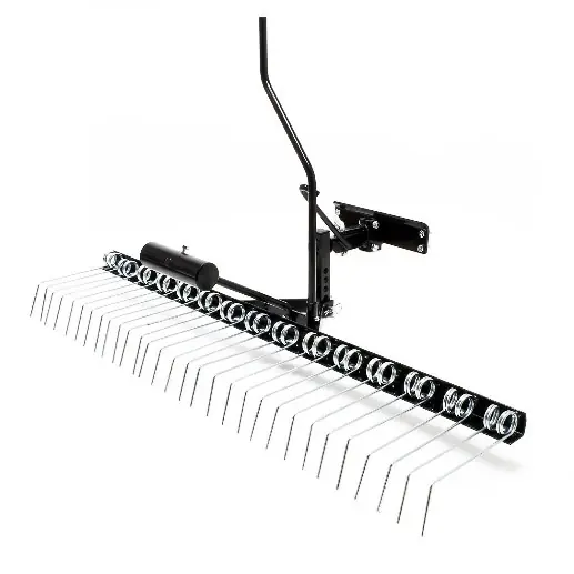
The XPOtool Dethatcher Lawn Comb (51704) is a towed garden implement designed for lawn maintenance. Before initial operation, ensure you have read and understood the entire manual. The device must be towed by a recommended vehicle, and users should always consult the towing vehicle's manual for proper operation.
Safety instructions
To minimize the risk of injury, observe the following precautions:
- Personal Safety: Always wear protective clothing, eye protection, gloves, and working boots while operating the device. Keep hands and feet away from moving parts.
- Operation: Never transport persons on the device. Never allow children to play on, stand, or climb on the device.
- Maintenance: Check the device before every use for loose parts or damage. Immediately replace or repair damaged or worn parts.
- Terrain: Drive around large holes and ditches. Reduce speed when working on steep slopes or impracticable ground.
Assembly
Follow these steps to assemble the dethatcher:
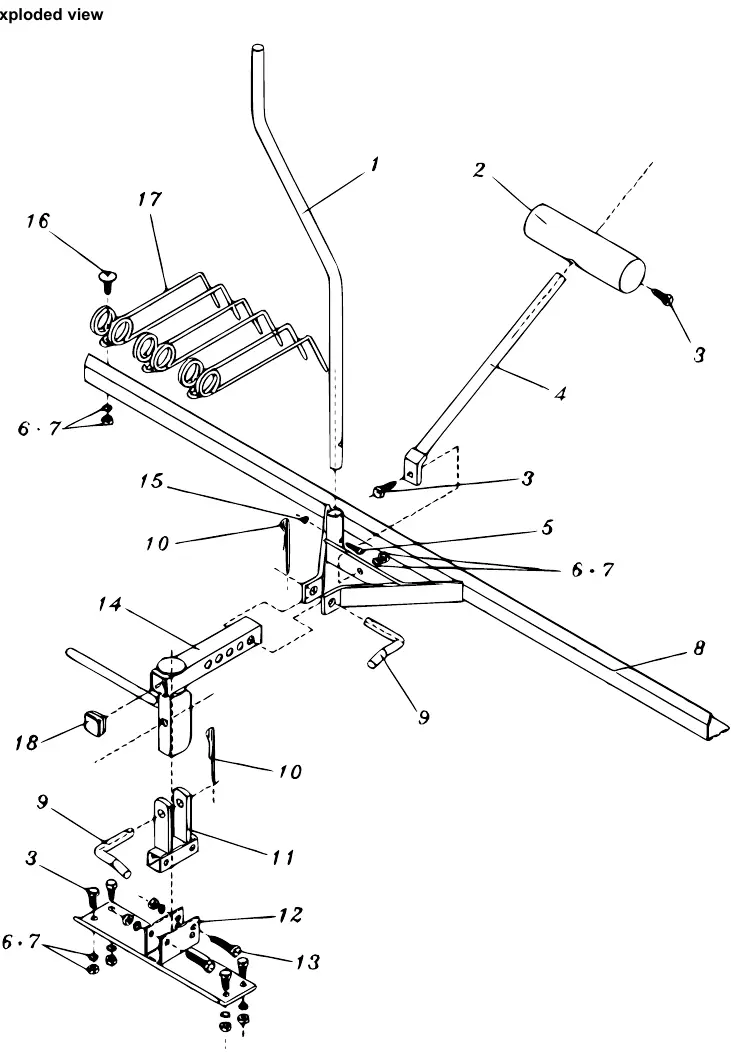
- Attach the spring tine (17) to the frame (8) using the round head bolt M8×20 (16), hexagonal nut M8 (6), and lock washer ⌀8 (7).
- Attach the lift handle (1) to the frame (8) using the hexagonal bolt M5×30 (5) and hexagonal nut M5 (15).
- Attach the adjusting rod (4) to the frame (8) using the hexagonal bolt M8×25 (3), hexagonal nut M8 (6), and lock washer ⌀8 (7).
- Attach the adjusting frame (14) to the frame (8) using a pin (9) and a hair cotter pin ⌀3 (10).
- Insert the plastic cap (18) into the adjusting frame (14).
- Attach the connector (11) to the bracket (12) using the hexagonal bolt M8×45 (13), hexagonal nut M8 (6), and lock washer ⌀8 (7). Tighten all screws.
- Attach the connector (11) to the bracket (12) using a pin (9) and a hair cotter pin ⌀3 (10).
- Connect the adjusting steel block (2) with the adjusting rod (4) and adjust for working depth.
- Use the hexagonal bolt M8×25 (3), hexagonal nut M8 (6), and lock washer ⌀8 (7) to connect the rake to the frame (8).
Parts list
The device consists of 18 components, including the frame, handle, adjusting rod, connector, bracket, and various fasteners (bolts, nuts, washers, pins). Refer to the exploded view diagram for the exact positioning of these parts.
Practical help
Common problems
Loose parts during operation
Check the device for loose parts before every use and tighten all screws.
Damaged or worn components
Immediately replace or repair any damaged parts before further use.
Difficulty on slopes or uneven ground
Always reduce your speed when working on impracticable ground, streams, or ditches.
Before use
- Read the entire user manual.
- Check the device for loose parts.
- Ensure the device is in good condition.
- Wear protective clothing, gloves, and boots.
- Secure and lock the hitch assembly before operating.
- Verify the towing vehicle is recommended for this device.
Specs in practice
- M8/M5 Bolts and Nuts
- Standard fasteners used for assembly; ensure they are tightened securely.
- Hair cotter pin ⌀3
- Securing pins for the connector and adjusting frame; ensure they are properly inserted.
Images and diagrams
- The exploded view illustrates the connection points between the frame, adjusting rod, and the hitch assembly.
- It highlights the sequence of fasteners (bolts, nuts, washers) required for each connection.
Model compatibility
- Only tow the device with vehicles recommended for such equipment.
- Always consult the towing vehicle's manual for proper towing procedures.

Manual page author
Emily Carter
User documentation editor
Prepares concise manual descriptions and highlights the most useful setup, operation, and maintenance information for readers.