Industrial / Electrical
10kW AIO Inverter & Battery Wiring Diagram & Configuration
Comprehensive wiring and configuration guide for 10kW All-In-One inverters, covering single-phase, split-phase, and three-phase system setups with battery integration.
Table of contents
System Overview
This guide provides essential wiring diagrams and configuration parameters for the 10kW All-In-One (AIO) inverter system. It is designed to assist installers and users in correctly connecting the inverter with solar arrays, battery storage, and grid inputs to ensure safe and efficient operation. The system supports various configurations, including single-phase, split-phase, and three-phase setups, allowing for scalable energy solutions.
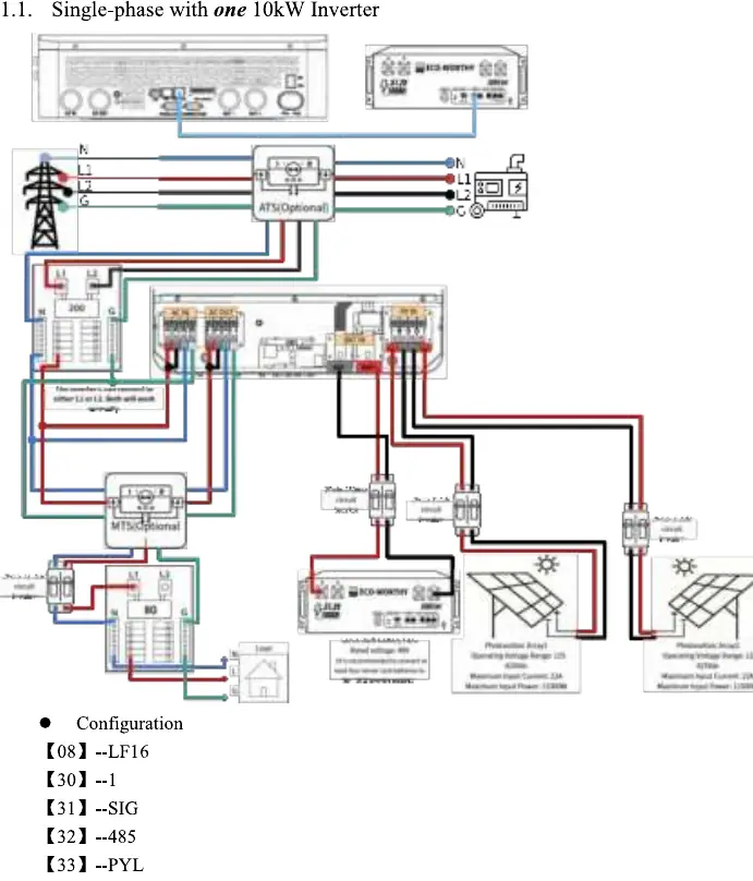
Single-Phase Connection
For single-phase installations, the inverter can be configured as a standalone unit or in parallel with a second unit. Proper wiring involves connecting the AC input/output, PV arrays, and battery terminals according to the provided diagrams. Configuration settings, such as battery type (LF16), communication protocols (PYL), and device IDs, must be accurately entered into the inverter menu to ensure seamless communication between the inverter and the battery management system.
Split-Phase and Three-Phase Configurations
The 10kW AIO inverter is highly versatile, supporting split-phase configurations for 208V or 240V systems. Depending on the specific power requirements, users can connect one, two, or three inverters. Each configuration requires specific parameter settings for device IDs and phase synchronization. For three-phase systems, three inverters are utilized, with each unit assigned a specific ID to manage the three-phase output correctly. It is critical to follow the wiring diagrams precisely to avoid phase mismatch or system errors.
Configuration and Settings
Successful system operation relies on correct parameter configuration. Users must navigate the inverter settings menu to adjust values such as battery communication (PYL), device ID (e.g., 1, 2, 3), and phase settings (e.g., 2P0, 2P1, 2P2). These settings ensure that the inverters operate in harmony, whether in a single-unit or multi-unit parallel configuration. Always verify that the firmware version matches the requirements for your specific setup.
Safety and Maintenance
Installation should only be performed by qualified personnel. Ensure all connections are secure and that the system is properly grounded. Regularly inspect the wiring for signs of wear or loose connections. Keep the inverter and battery area clean and well-ventilated to prevent overheating. If the system displays error codes, refer to the configuration settings to ensure all parameters are correctly set for your specific installation type.
Practical help
Common problems
Inverter not communicating with battery
Verify that parameter [33] is set to PYL and that the communication cable is securely connected.
Phase mismatch in multi-inverter system
Ensure that device IDs [30] and phase settings [31] are configured correctly for each unit as per the wiring diagram.
Before use
- Ensure all AC and DC breakers are in the OFF position before wiring.
- Verify that the battery voltage matches the inverter input requirements.
- Check that all cable connections are tight and properly insulated.
- Confirm that the grounding wire is connected to a reliable earth point.
- Ensure the installation environment is dry and well-ventilated.
- Verify that the PV array voltage is within the inverter's operating range.
Images and diagrams
- Wiring diagrams illustrate the connection between the grid, inverter, battery, and solar panels.
- Blue lines typically represent Neutral, Red/Black represent Live/DC lines, and Green represents Ground.
- ATS (Automatic Transfer Switch) and MTS (Manual Transfer Switch) are shown as optional components for grid-backup scenarios.
Model compatibility
- Designed for use with LiFePO4 server rack batteries.
- Supports parallel operation for increased power capacity.
- Compatible with both 208V and 240V split-phase electrical systems.

Manual page author
Michael Turner
Technical manual editor
Reviews PDF manuals for structure, safety notes, and practical product details so readers can find the right information quickly.