Industrial / Temperature Controllers
User Manual for AKO-17630 and AKO-17631 PROCool Electronic Panel
Comprehensive user guide for the AKO-17630 and AKO-17631 PROCool Electronic Panel. Includes detailed installation instructions, wiring diagrams for pressure controllers, technical specifications, and essential maintenance procedures.
Table of contents
Manual images
Click an image to enlargeQuick Guide
This document provides essential information for the installation, operation, and maintenance of the AKO-17630 and AKO-17631 PROCool Electronic Panels. Always disconnect the power supply before performing any work inside the electrical panel. Wiring must be performed by authorized staff in accordance with current standards and the provided diagrams.
Description of Indicators
The front panel features several indicators to monitor the system status:
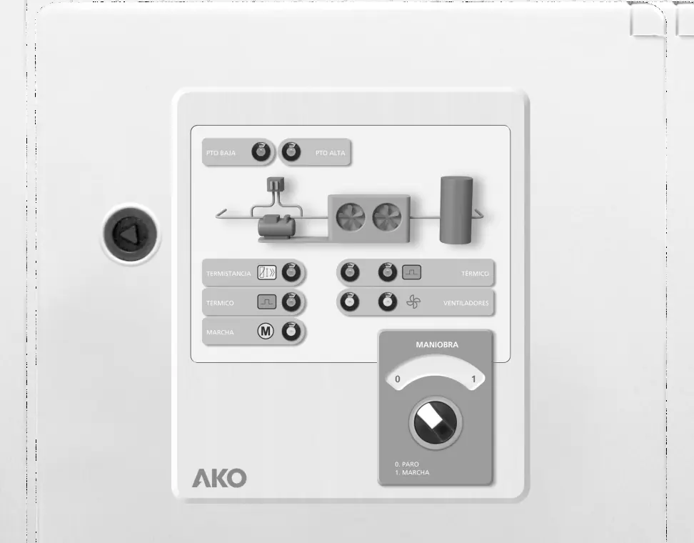
- Low/High pressure switch indicators: Monitor system pressure status.
- Compressor thermistor/thermal relay indicators: Monitor compressor health and protection status.
- Fans running/thermal relay indicators: (AKO-17631 only) Monitor fan operation and protection status.
- Stop/Run selector: Used to manually control the system operation.
Technical Specifications
- Rated voltage (Un): 400 V~ ±10 % 50/60 Hz ±5 %
- Rated voltage (Ue): 230 V~ ±10 % 50/60 Hz ±5 %
- Maximum nominal input current: 32 A
- Maximum input power: 30 VA
- Operating temperature: -5 ºC to 40 ºC
- Storage temperature: -30 ºC to 70 ºC
- Degree of protection: IP65
- Dimensions (AKO-17630): 400 x 300 x 165 mm
- Dimensions (AKO-17631): 500 x 400 x 175 mm
Installation Recommendations
Proper installation is critical for safety and performance:
- Ensure a clean safety space around the panel without obstacles.
- Do not knock or make sudden movements on the panel.
- Use circuit breakers of the phase/s + neutral, curve C type.
- The panel is designed for fixed internal assembly.
- Ensure earth terminals are connected to guarantee earthing continuity (earthing must be carried out outside the panel).
- The neutral ratings are of the TT type; do not use the IT rating.
Checks Before and During Start-up
Before starting the panel, perform the following checks:
- Verify that power supply voltages and frequencies match the technical specifications.
- Check for loose parts, foreign bodies, dust, or dampness inside the panel.
- Ensure all switchgear and components are correctly fastened and screws are tightened.
- Verify the correct connection of power conductors and insulation of outer lines.
- Check that motor guard settings (FK1, FK2, FK3) are correct for the specific model.
- It is recommended to preheat the compressor's housing before start-up.
During start-up, ensure no electric arcs occur, relays/contactors do not produce ratios, and there is no overheating in cables or controllers.
Maintenance
- Periodical maintenance: Keep the panel closed using its lock.
- Annual checks: Retighten power connections and check the wear of the switchgear once a year.
- Cleaning: Clean the outer surface with a soft cloth, water, and detergent. Do not use abrasive detergents, petrol, white spirits, or solvents.
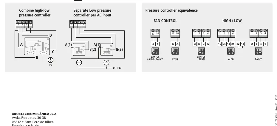
Pressure Switch Wiring Options
The panel supports various pressure controller configurations. Refer to the wiring diagrams for specific connections regarding high/low pressure controllers and fan control. Ensure all wiring follows the specific diagrams provided for your controller type (e.g., Danfoss, Alco, Ranco, Penn).
Manufacturer information
AKO Group
Practical help
Common problems
Overheating in cables or switchgear
Check connections and retighten power connections. Ensure no loose parts or foreign bodies are present.
Panel access
A tool is required to remove any fixed part of the panel.
Wiring errors
Only carry out wiring foreseen in the provided wiring diagrams. Ensure authorized staff performs the work.
Before use
- Verify power supply voltage and frequency match specifications.
- Check for loose parts or foreign bodies on connections.
- Ensure no dust or dampness inside the panel.
- Verify correct fastening and tightening of screws and power connections.
- Check motor guard settings (FK1, FK2, FK3).
- Preheat the compressor's housing.
Specs in practice
- TT type neutral
- The system is designed for TT earthing systems; do not use IT rating.
Images and diagrams
- The wiring diagrams illustrate how to connect high-low pressure controllers.
- Specific diagrams are provided for different controller brands including Danfoss, Alco, Ranco, and Penn.
- Diagrams show the necessary connections for fan control and high/low pressure inputs.
Model compatibility
- Compatible with TT type neutral systems.
- IT rating systems should not be used.
- Terminals are designed for copper external conductors.

Manual page author
Emily Carter
User documentation editor
Prepares concise manual descriptions and highlights the most useful setup, operation, and maintenance information for readers.