Industrial / Temperature Controllers
Advanced Temperature Controller AKO-16526A / AKO-16526AN User Manual
Quick guide and configuration manual for the AKO-16526A and AKO-16526AN advanced temperature controllers. Includes installation, wiring, setup wizard, and troubleshooting.
Table of contents
Manual images
Click an image to enlargeQuick Start Guide
The AKO-16526A / 16526AN controller features a SELFDRIVE operating mode that automatically manages fans and defrost cycles to optimize cold room performance. Upon first power-up, the unit enters the ASSISTANT mode. Use the arrow keys to change values and the SET button to accept and proceed to the next step.
Device Description
The controller is designed for cold room stores and includes an output for electronic expansion valve regulation. The AKO-16526AN model includes an NBIoT communication module for autonomous data transmission to akonet.cloud.
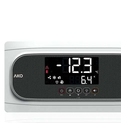
Keypad Operation
- Stand-By: Press for 3 seconds to activate/deactivate.
- Defrost: Press for 3 seconds to start/stop.
- Light: Short press to toggle cold room light.
- Programming: Press SET for 3 seconds for condensed menu, 6 seconds for extended menu.
- Set Point: Short press to view current set point; press for 3 seconds to adjust.
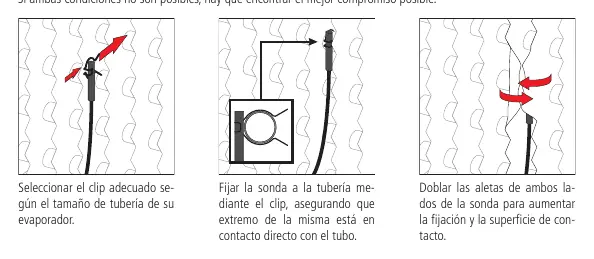
Installation of Probes
Correct probe installation is critical for thermal transfer calculation and defrost management.
- Ambient Probe: Place in an area not directly receiving cold air from the evaporator, preferably in the air aspiration zone.
- Evaporator Probe: Place as close as possible to the refrigerant inlet (near the expansion valve) in the finned area. If using electric defrost, place away from heating elements.
- Fixing: Use the provided clips for 10-25 mm pipes. Ensure direct contact with the tube and bend probe fins to increase contact surface.
Setup Wizard
The assistant guides you through initial configuration:
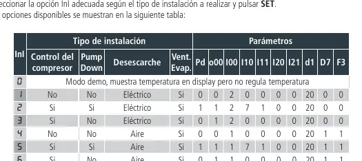
- Step 1: Select the installation type (InI option) from the provided table (e.g., compressor control, pump down, defrost type).
- Step 2: Define the refrigerant gas type (u02).
- Step 3-4: Define pressure sensor range (I62/I63) if applicable.
- Step 5: Set temperature set point.
- Step 6: Choose whether to set remaining parameters to default.
Operation and Messages
The display shows various status icons and error codes. Common messages include:
- Pd / LP: Pump down malfunction (Stop/Start).
- E1-E6: Sensor fault (open or crossed circuit).
- Ad0: Open door alarm.
- HCP: HACCP alarm.
- dEF: Defrost in progress.
Technical Specifications
The controller operates on 100-240 V ~ 50/60 Hz. It features multiple relay outputs (DEF, FAN, COOL, AUX1-3) with varying current ratings. The unit is IP65 rated when the cover is closed and properly installed with glands. Operating temperature range is -10 ºC to 50 ºC.
Official resources from the manual
Manufacturer information
AKO Group
Practical help
Common problems
Pd / LP error
Pump down malfunction. Check parameters C19 and C20.
E1-E6 error
Sensor faulty. Check for open or crossed circuits.
Ad0 alarm
Open door alarm. Check if the door has been open longer than parameter A12.
HCP alarm
HACCP alarm. Temperature reached h1 threshold for longer than h2.
Before use
- Ensure power supply is 100-240 V ~ 50/60 Hz.
- Verify probe type (NTC or Pt1000) and ensure all connected probes are identical.
- Install in a location protected from vibrations, water, and corrosive gases.
- Ensure IP65 protection by closing the cover and using appropriate glands.
- Check wiring against the enclosed schematic before powering on.
Images and diagrams
- Probe installation: Use clips for 10-25mm pipes, ensure direct contact, and bend fins for better thermal transfer.
- Keypad: Icons indicate status of Stand-by, Door, Alarm, Fans, Cool, Selfdrive, Compressor, Defrost, and Light.
Model compatibility
- Supports NTC or Pt1000 probes (must be consistent across all inputs).
- AKO-16526AN includes NBIoT communication for akonet.cloud.

Manual page author
Emily Carter
User documentation editor
Prepares concise manual descriptions and highlights the most useful setup, operation, and maintenance information for readers.