Industrial / Temperature Controllers
User Manual for AKO-16524A, AKO-16525A, and AKO-16525AN Temperature Controller
Quick guide for the AKO-16524A, AKO-16525A, and AKO-16525AN advanced temperature controllers. Includes installation, wiring, configuration, troubleshooting, and technical specifications.
Table of contents
Manual images
Click an image to enlargeQuick guide from the manual
Upon first power-up, the unit enters the ASSISTANT mode. The display will show the message InI flashing at 0. Select the appropriate option based on your installation type and press SET. After the wizard, enter the desired Set Point value and press SET. The unit will then begin temperature regulation.
Device description
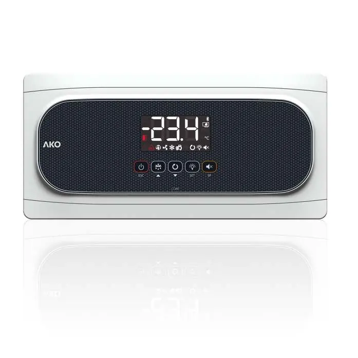
The controller features a display and a keypad. Indicators show the status of the Stand-By mode, door status, alarms, SELFDRIVE mode, evaporator fans, solenoid, compressor, defrost relay, continuous cycle mode, and cold room light. The AKO-16525AN model also indicates NBIoT network registration status.
Installation
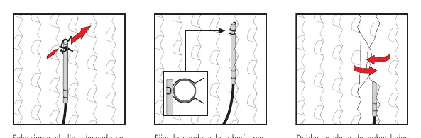
Correct probe installation is critical for performance. The kit includes a 4 mm hermetic evaporator probe (1.5 m cable) and an ambient probe, along with various mounting clips. The ambient probe should be placed away from direct cold air flow. The evaporator probe should be placed near the refrigerant inlet in the finned area.
Initial configuration
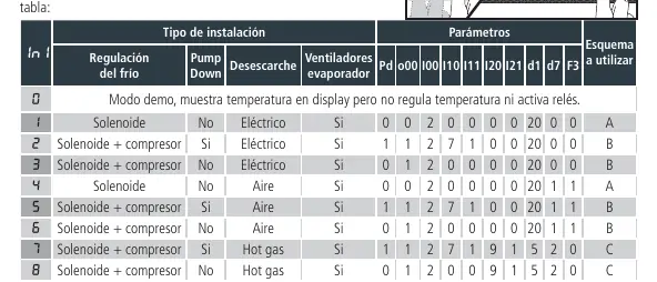
The configuration wizard guides you through the setup. Select the installation type (0-8) to automatically configure parameters. If you need to reactivate the wizard, activate Stand-By mode (press the Stand-by key for 3 seconds), wait for the indicator to light up permanently, and press the keys in this order: Up, Down, SET.
Operation
The controller manages temperature regulation, defrost cycles, and fan operation. The SELFDRIVE mode periodically evaluates heat transfer to optimize resources. If an alarm occurs, the display will show specific codes. For the AKO-16525AN, registration on akonet.cloud is required for data transmission. Force the first transmission by pressing ESC and SET for 3 seconds.
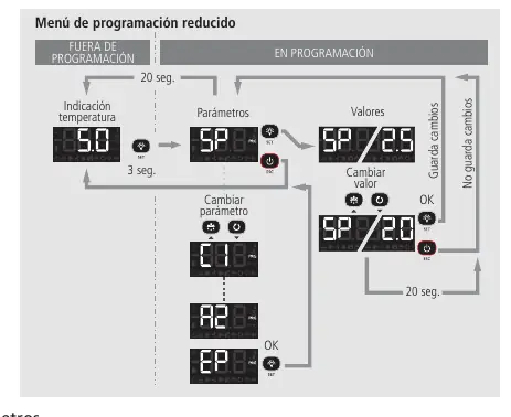
Programming
The controller offers two programming menus: Condensed (press SET for 3 seconds) for frequently used parameters, and Extended (press SET for 6 seconds) for full configuration. Use the Up and Down keys to navigate and modify values, and press SET to accept.
Troubleshooting
The device displays error codes to assist in diagnostics. Common errors include probe failures (E1/E2/E3), defrost errors (E10/E20), and calibration stability issues (E12/E22). Refer to the troubleshooting section for specific solutions, such as checking probe wiring or ensuring the cold room door remains closed during calibration.
Technical specifications
The unit operates on 100-240 V~ 50/60 Hz. It features IP65 protection. Relay outputs are rated for various loads (16A/20A). The probe temperature range is -50.0 ºC to 99.9 ºC. The AKO-16525AN model includes internal NBIoT connectivity.
Official resources from the manual
Manufacturer information
AKO Group
Practical help
Common problems
E1/E2/E3 (Probe failure)
Check the condition and wiring of the affected probe.
E12/E22 (Calibration stability error)
Avoid opening the cold room door during calibration. Check refrigeration circuit components, especially the aspiration part.
E17 (Excessive door openings during calibration)
Ensure the cold room door remains closed during the calibration process.
E15/E25 (SELFDRIVE deactivation)
Check refrigeration circuit components and probe positions. Restart the device to return to SELFDRIVE mode.
Before use
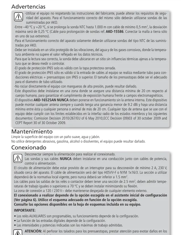
- Disconnect power supply before performing any wiring.
- Use only AKO-supplied NTC probes.
- Ensure the installation site is protected from vibrations, water, and corrosive gases.
- Verify that the power supply cable is H05VV-F or NYM 1x16/3 type.
- Ensure the 120/230 V~ wiring area is kept clear of external elements.
- For AKO-16525AN, ensure sufficient NBIoT coverage at the installation site.
Specs in practice
- Power Supply
- 100 - 240 V~ 50/60 Hz
- Protection Degree
- IP65 (valid only with protection cover closed and proper cable glands)
- Nominal Current
- 15 A maximum
Images and diagrams
- Wiring depends on the option selected in the initial configuration wizard.
- Consult the specific diagram sheet included with your device based on the chosen configuration.
Model compatibility
- NBIoT connectivity is exclusive to the AKO-16525AN model.
- Bluetooth functionality requires an optional CAMM module.

Manual page author
Michael Turner
Technical manual editor
Reviews PDF manuals for structure, safety notes, and practical product details so readers can find the right information quickly.