Power / Batteries & Chargers
Danfoss EKC 102C1 Temperature Controller Operating Instructions
Quick guide for the Danfoss EKC 102C1 temperature controller. Learn how to set parameters, configure defrost cycles, manage alarms, and perform a factory reset.
Table of contents
Quick Guide
The Danfoss EKC 102C1 is a temperature controller designed for refrigeration applications. Regulation starts automatically when voltage is applied. Users should review factory settings and adjust parameters as needed for their specific installation.
Operation
The controller is operated using three buttons on the front panel:
- Set Menu: Push the upper button until a parameter is shown. Use the upper or lower button to navigate to the desired parameter. Push the middle button to display the value. Use the upper or lower button to change the value, then push the middle button to confirm.
- Set Temperature: Push the middle button until the temperature value is shown. Use the upper or lower button to select the new value, then push the middle button to confirm.
- View Other Sensor: Push the lower button briefly to see the temperature at the other sensor.
- Manual Defrost: Push and hold the lower button for four seconds to start or stop a defrost cycle.
- View Alarm Code: Push the upper button briefly.
Defrost Management
Defrosting can be configured via parameters:
- d01: Defrost method (0=none, 1=natural, 2=gas).
- d02: Defrost stop temperature.
- d03: Interval between defrost starts.
- d04: Maximum defrost duration.
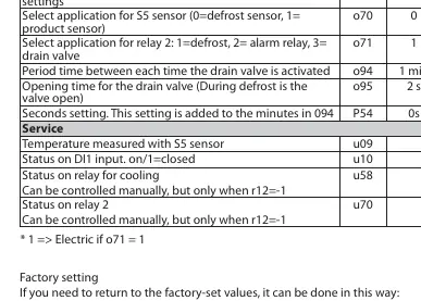
Factory Reset
To return the controller to factory-set values:
- Disconnect the supply voltage to the controller.
- Keep the upper and lower buttons depressed simultaneously.
- Reconnect the supply voltage while holding the buttons.
Alarm and Status Codes
The display indicates system status and alarms:
- Alarm Codes: A1 (High temperature), A2 (Low temperature), A4 (Door alarm), A45 (Standby mode).
- Fault Codes: E1 (Fault in controller), E27 (S5 sensor error), E29 (Sair sensor error).
- Status Codes: S0 (Regulating), S14 (Defrosting), S17 (Door open), -d- (Defrost in progress).
Technical Specifications
- Supply Voltage: 230 V a.c. 50/60 Hz
- Power Consumption: 1.5 VA
- Ambient Temperature: 0 to +55°C
- Sensor Compatibility: Pt 1000, Ptc 1000, NTC-M2020
- Relay Load: 10(6) A / 16 A relays
Manufacturer information
Danfoss A/S
Practical help
Common problems
Alarm flashing on display
Press the upper button briefly to view the alarm code (A1, A2, A4, A45) and identify the cause.
Defrost cycle not starting
Check parameter d01 (Defrost method) and d03 (Interval between defrost starts). Ensure the controller is not in standby mode.
Controller not regulating
Check parameter r12. If set to -1, regulation is stopped. Ensure the unit is not in standby mode (A45).
Before use
- Verify supply voltage is 230V AC.
- Ensure the correct sensor type (Pt, PTC, or NTC) is selected in parameter o06.
- Check that the load connected to the relays does not exceed 10A (Resistive) or 16A.
- Confirm wiring matches the diagrams provided on page 1 of the manual.
- Review factory settings and adjust parameters (r01-r13, d01-d19) to match your application requirements.
Specs in practice
- r01 (Differential)
- The temperature difference between the cut-out and cut-in points.
- d01 (Defrost method)
- Determines how defrosting is performed: 0=None, 1=Natural, 2=Gas.
- o06 (Used sensor type)
- Configures the controller for the specific sensor installed (Pt, PTC, or NTC).
- o71 (Relay 2 application)
- Configures the function of relay 2: 1=Defrost, 2=Alarm, 3=Drain valve.
Images and diagrams
- The wiring diagrams on page 1 illustrate connections for the 230V power supply, compressor, defrost heater/valve, and sensors (S5, Sair, DI1).
- The diagrams distinguish between different relay configurations and sensor inputs.
Model compatibility
- Compatible with Pt 1000 (1000 Ohm / 0°C), Ptc 1000 (1000 Ohm / 25°C), and NTC-M2020 (5000 Ohm / 25°C) sensors.

Manual page author
Emily Carter
User documentation editor
Prepares concise manual descriptions and highlights the most useful setup, operation, and maintenance information for readers.