Industrial / Circuit Breakers
Installation Instructions for Allen Bradley 1494F Flange Mounted Disconnect Switches
A comprehensive installation guide for Allen Bradley 1494F flange-mounted disconnect switches. This manual covers enclosure construction, switch mounting, fuse block installation, and door hardware setup.
Table of contents
Manual images
Click an image to enlargeQuick Guide from the Manual
This document provides installation instructions for the Allen Bradley 1494F Flange Mounted Disconnect Switches. It covers enclosure construction, switch mounting, fuse block installation, and door hardware assembly. Note that all drawings in this manual are for a right-hand flange installation; left-hand installations have diametrically opposite dimensions.
Enclosure Construction
Before installation, ensure the enclosure meets the required dimensions based on the NEMA size and fuse clip type. Guidelines for enclosure selection are as follows:
- Small Enclosures: 30 inches high or less with 2 or 3 point latching.
- Intermediate Enclosures: 30 to 48 inches high with 3 point latching.
- Large Enclosures: Above 48 inches high with 3 point latching.
Ensure adequate wire bending space as required by the National Electrical Code (N.E.C.). If using pressure connectors other than Allen-Bradley, adjust dimensions accordingly.
Disconnect Switch Installation
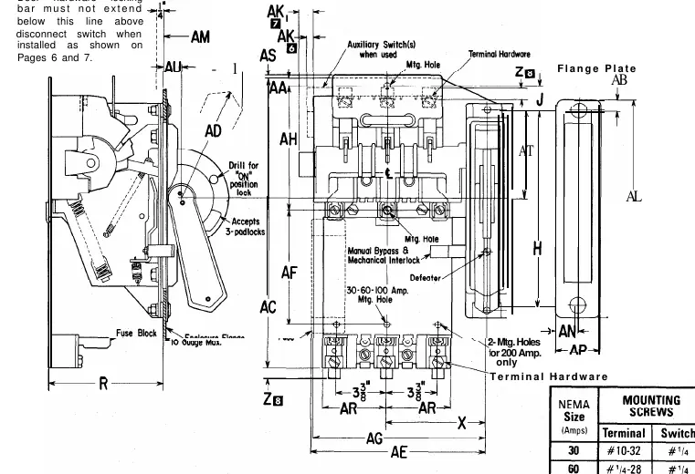
- Remove nuts and washers from the flange plate.
- Place the disconnect switch into the enclosure with the operating handle in the "Off" position.
- Tilt the assembly under the flange and bring the handle through the provided slot.
- Place flange plate studs through the holes in the flange and mechanism frame while holding the assembly against the underside of the flange. Secure the assembly to the flange.
- Attach the disconnect switch firmly to the enclosure mounting plate surface.
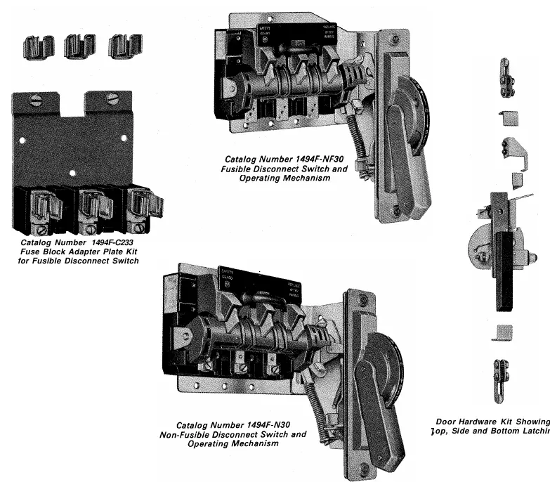
Fusible Disconnect Switch Installation
- Attach fuse clips provided with the fuse block adapter plate kits to the disconnect switch terminals.
- Attach the fuse block adapter plate to the disconnect switch mounting bracket.
- Secure the fuse block adapter plate to the enclosure mounting plate surface.
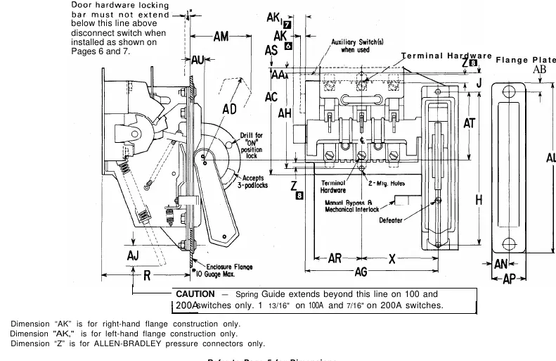
Door and Hardware Construction
The door hardware installation involves setting up the locking bar and handle assembly. Ensure the door catch and guide brackets are properly located using the specified dimensions (P and T). If specific installation permits, holes can be drilled in the door catch and guide bracket using the projections as centers.
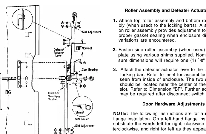
Door Hardware Adjustments
After installing the door hardware and securing the disconnect in the "Off" position:
- Close the enclosure door and turn the handle to the right until the first notch on the cam plate engages to ensure a positive gasket seal.
- If necessary, relocate the defeater actuator lever so the disconnect "On" position occurs before the fully latched door handle position.
- Test the door opening mechanism by turning the recessed door defeater screw while turning the handle to the left.
Manufacturer information
Allen-Bradley
Practical help
Common problems
Door does not clear the flange plate
Ensure a 3/32 inch minimum clearance. A smaller dimension increases 'U' and 'E' by 3/16 inch minimum and 'G' by 3/8 inch minimum.
Disconnect switch handle moves to 'On' position before door is fully latched
Relocate the defeater actuator lever so the 'On' position occurs well before the fully latched (vertical) door handle position.
Before use
- Verify enclosure size (Small, Intermediate, or Large) based on height and latching points.
- Check NEMA size and fuse clip type.
- Confirm right-hand or left-hand flange installation requirements.
- Ensure N.E.C. wire bending space requirements are met.
- Verify that the door hardware kit matches the enclosure size.
Images and diagrams
- Right-hand flange installation is standard; left-hand installation dimensions are diametrically opposite.
Model compatibility
- Designed for Allen-Bradley pressure connectors; using other connectors may require dimension adjustments.
- Door catch supplied with all disconnects is not to be used with the optional door hardware kits.

Manual page author
Michael Turner
Technical manual editor
Reviews PDF manuals for structure, safety notes, and practical product details so readers can find the right information quickly.