Industrial / Disconnect Switches
User Manual for Allen-Bradley 140MT-C3E Motor Protection Circuit Breaker
Comprehensive user guide for the Allen-Bradley 140MT-C3E and 140MT-D9 series motor protection circuit breakers. Includes installation procedures, wiring diagrams, torque specifications, hazardous location (Ex) compliance, and maintenance...
Table of contents
Manual images
Click an image to enlargeQuick Guide from the Manual
This document provides installation and operation instructions for the Allen-Bradley 140MT-C3E and 140MT-D9 series Motor Protection Circuit Breakers. These devices are designed for motor protection and must be installed by qualified personnel in accordance with local safety regulations. Important: The 140MT-D9N model is not suitable for Ex (hazardous location) applications.
Installation and Wiring
Proper installation is critical for safety and device performance. Follow these steps for a proper connection:
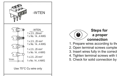

- Prepare wires according to the instructions.
- Open terminal screws completely.
- Insert wires fully into the correct position.
- Tighten terminal screws with the required torque.
- Check for a solid connection by pulling on all wires.
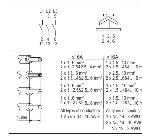
Wiring Requirements: Use 75°C Cu wire only. Ensure the cable type and conductor cross-section are selected to prevent exceeding thermal limiting temperatures.
Operation and Settings
The device acts as a thermally delayed release with phase failure protection. To ensure proper motor protection:
- Current Setting: Set the device to 105% of the motor current.
- Warning: Do not set the current outside the specified scale.
- Testing: The tripping mechanism can be tested in the de-energized state using the device's test function.
Maintenance and Safety
The product contains no serviceable parts. If the device is faulty, it must be replaced. Regular maintenance includes:
- Periodic external inspection.
- Cleaning dust from the device.
- Checking the tightness of all terminals and bus bar connections.
- Examining current-carrying components after an overload or fault current interruption; replace if damaged.
Ex Relevant Information
For devices used in hazardous locations (Ex zones):
- Mining: db, eb, and pxb ignition protection.
- Gas: db, eb, and pxb ignition protection.
- Dust: tb and pxb ignition protection.
- Restrictions: No repairing of 140MT-C/D devices is allowed, as the Ex protection function will no longer be guaranteed.
- Ambient Temperature: Operation at -25°C to +60°C; Storage at -40°C to +80°C.
Technical Specifications
The device meets IEC 60947-2 and is cULus listed. It serves as a Manual Motor Controller with optional approvals for Group Motor, Motor Disconnect, and Tap Conductor Protection. Refer to the short circuit ratings table in the full manual for specific kA ratings based on voltage and installation type.
Manufacturer information
Allen-Bradley
Practical help
Common problems
Device trips due to overload or fault
Check circuits to determine the cause. Examine current-carrying components and replace if damaged. Replace integral current sensors if a fault condition existed.
Loose terminal connections
Regularly check the tightness of all terminals and bus bar connections to prevent overheating.
Automatic restart after failure
If automatic restarting is not permitted, the user must take suitable measures to prevent restarting.
Before use
- Ensure installation is performed by qualified personnel.
- Verify that the power is disconnected before installation.
- Use only 75°C Cu wire.
- Ensure the current setting is adjusted to 105% of the motor current.
- Check that the device is not damaged mechanically or electrically before installation.
- Verify the model is appropriate for the application (e.g., 140MT-D9N is not for Ex applications).
Specs in practice
- 105% of motor current
- The required setting for the overload protection mechanism.
- 75°C Cu wire
- The mandatory wire temperature rating for safe operation.
- Ex eb Mb / Ex eb Gb
- Hazardous location protection ratings for mining and gas environments.
Images and diagrams
- Wiring diagram: Shows L1, L2, L3 inputs and T1, T2, T3 outputs for 1- or 2-phase applications.
- Torque settings: Indicates the required torque (2-2.5 Nm or 3-3.5 Nm) for terminal screws.
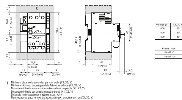
- Dimensions: Provides X1, X2, Y, and Z clearance distances for installation.
Model compatibility
- 140MT-D9N is not usable for Ex applications.
- Device meets IEC 60947-2 and is cULus listed.
- Suitable for Group Motor, Motor Disconnect, and Tap Conductor Protection.

Manual page author
David Miller
Documentation analyst
Organizes user manual content into clear summaries, with attention to model details, product context, and everyday usability.