Lighting / Disconnect Switches
Installation Manual for Ideal PowerPlug Disconnect 103G
Comprehensive installation guide for the Ideal PowerPlug Disconnect Model 103G. Includes wiring instructions, electrical ratings, wire gauge compatibility, and safety procedures for grounding applications.
Table of contents
Manual images
Click an image to enlargeQuick Guide from the Manual
The Ideal PowerPlug Disconnect Model 103G is a current-rated device designed for grounding applications. Important: This product is for COPPER TO COPPER ONLY. Do not use with Aluminum wiring. The device is rated for a maximum of 600 Volts and 6 Amps. Always turn off power at the circuit breaker or remove the fuse before installing or removing the device.
Conductor Installation
- Ensure all wiring complies with local electrical codes.
- Turn off power before starting installation.
- Strip wires to 3/8 inch (9.5 mm). For 18 AWG wire, you may strip between 3/8 inch to 1/2 inch.
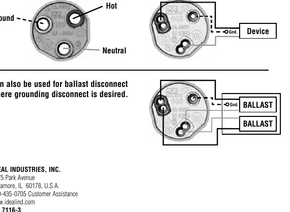
- Load Side (Green Cap): Grip the black load wire firmly and push it into the port marked with black. Grip the white load wire and push it into the port marked with white.
- Grounding: Grip the ground wire firmly and push it into the port marked with a green circle.
- Line Side (White Cap): Grip the black supply wire and push it into the port opposite the black load wire (marked with a black circle). Grip the white supply wire and push it into the port opposite the white load wire (marked with a white circle).
- Ensure only one conductor is used per port and that no copper is exposed.
Note: The wire insertion side of this product is for ONE TIME USE ONLY. Do not remove and replace wires.
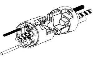
Disconnect De-mate / Mate Installation
- To de-mate: Grasp the disconnect at each end and pull apart to separate the halves. Do not pull on the wires.
- To mate: Grasp each disconnect half, align them, and push together until connected.
Technical Specifications
- Voltage/Amperage: 600 Volts / 6 Amps maximum.
- Temperature Rating: 105°C (221°F) maximum.
- Flame Rating: UL94V-0.
- Wire Range (Line Side - White Cap): Solid 12-18 AWG; Stranded 12-14 AWG (19 strand or less); Stranded Tin Bonded 12-14 AWG (19 strand or less), 16 AWG (26 strand or less), 18 AWG (16 strand or less).
- Wire Range (Load Side - Green Cap): Solid 18 AWG; Stranded Tin Bonded 18 AWG (16 strand or less).
Practical help
Common problems
Need to remove or replace wires
The wire insertion side is for one-time use only. Do not remove or replace wires; replace the entire device.
Using Aluminum wiring
Do not use. This product is for Copper to Copper connections only.
Electrical fire risk
Ensure the application does not exceed the 600V/6A rating and that wiring complies with local codes.
Before use
- Turn off power at the circuit breaker or remove the fuse.
- Verify that all wires are Copper (no Aluminum).
- Check that wire gauge is within the specified range (12-18 AWG).
- Strip wires to exactly 3/8 inch (9.5 mm) (18 AWG can be up to 1/2 inch).
- Ensure you have the correct side for Line (White Cap) and Load (Green Cap).
Specs in practice
- 600 Volts / 6 Amps
- Maximum electrical capacity of the device.
Images and diagrams
- Line Side (White Cap): Contains 3 ports for supply wiring.
- Load Side (Green Cap): Contains 5 ports for device or ballast wiring.
- Grounding: Ports marked with a green circle are designated for ground wires.
Model compatibility
- Copper to Copper only.
- Not compatible with Aluminum wiring.
- One-time use only; do not reuse ports.

Manual page author
David Miller
Documentation analyst
Organizes user manual content into clear summaries, with attention to model details, product context, and everyday usability.