HVAC / Parking Heaters
Installation Manual for Aussie Traveller 12V 2kW Diesel Heater
Comprehensive installation guide for the Aussie Traveller 12V 2kW Diesel Heater. Includes detailed mounting instructions, fuel line routing, wiring diagrams, controller installation, and technical specifications.
Table of contents
Manual images
Click an image to enlargeQuick guide from the manual
This manual provides instructions for the installation and operation of the Aussie Traveller 12V 2kW Diesel Heater. Before starting, ensure the heater is not mounted near flammable sources, in closed spaces without ventilation, or near water sources. Always protect the heater from road debris and splashing.
Product Description
The heater is a small fuel furnace controlled by a micro-processor, designed to warm caravans or RVs. It features automatic altitude adjustment (up to 5000m) and a whisper-quiet operation.
- Output: 2000W
- Voltage: 12V
- Fuel Consumption: 0.12–0.24L/hr
- Power Consumption: 14–29W
- Weight: 2.6kg
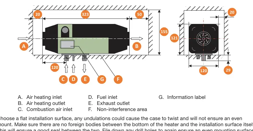
- Dimensions: 323x120x121mm
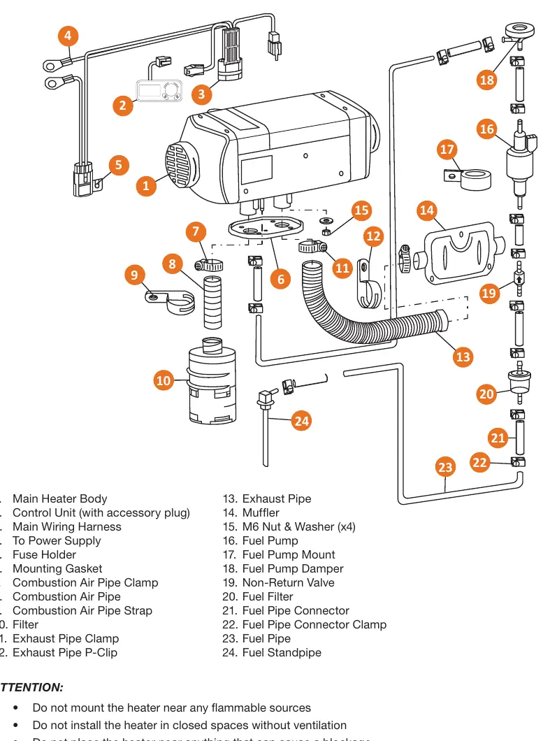
Installation of the Main Heater Body
Choose a flat installation surface to prevent case twisting. Ensure no foreign bodies are between the heater and the surface. File down any drill holes to ensure an even mounting surface. Tighten the M6 bolts to a torque setting of 6Nm+1Nm. If the installation area is less than 1.5mm thick, a mounting plate is required.
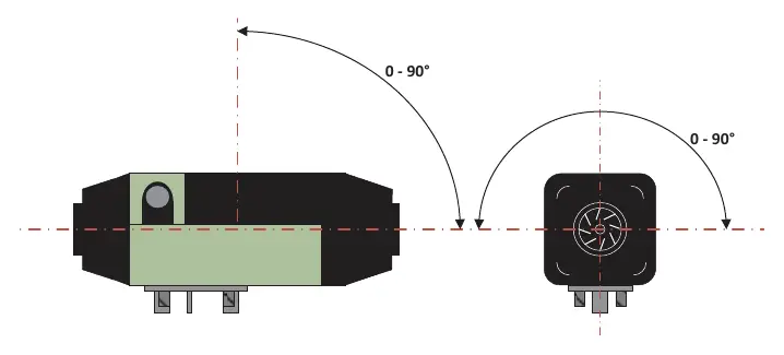
Installation of Combustion Air Pipe & Exhaust
The combustion air inlet pipe and exhaust pipe should exit at the bottom of the vehicle, facing opposite to the direction of travel. Ensure the exhaust vent points downward at an angle of 90°±10°. The sum of all curves in the pipes must not exceed 270°, and the radius of any curve must be no smaller than 50mm.
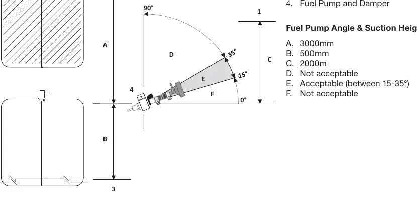
Installation of Fuel Lines
The fuel pump must be secured on an anti-vibration mount with the outlet tilted upward at an angle between 15° and 35°. The fuel line should ideally be placed uphill to the fuel pump to prevent air bubbles. Note: The fuel filter, fuel pipe, and clamps must be replaced every 2 years.
Wiring and ECU Connections
The main wiring harness connects to the controller socket (X6). Use a 25A fuse for 12V heaters. Ensure all exposed wires outside the vehicle are protected from road debris. The controller case interfaces are clearly marked for specific components (Fan motor, Glow plug, Overheat sensor, Fuel pump).
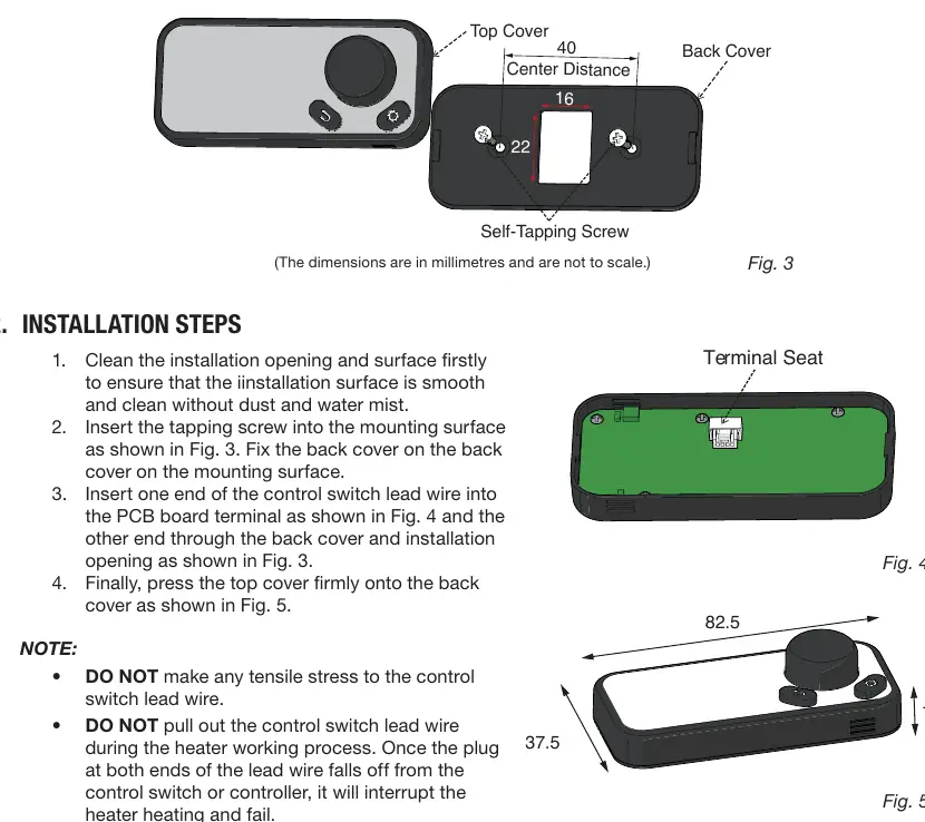
Controller Installation
The control switch should be installed in a waterproof and moisture-proof location within the driver's field of vision. The opening size required is 16 x 22mm. Do not apply tensile stress to the control lead wire.
Warranty Information
The product includes a 12-month warranty from the date of purchase. Warranty claims require proof of purchase, description of damage, and photos. Exclusions apply for improper installation, unauthorized modifications, or use in abnormal conditions.
Practical help
Common problems
Heater not starting or running poorly
Check fuel lines for air bubbles and ensure the fuel pump outlet is tilted upward at 15-35°.
Fuel flow issues
Ensure the fuel line is routed uphill to the fuel pump to assist with bleeding.
Uneven mounting
Ensure the installation surface is flat, free of foreign bodies, and drill holes are filed smooth.
Before use
- Check for missing parts upon unpacking.
- Ensure the installation surface is flat and clean.
- Verify the fuel pump is secured on an anti-vibration mount.
- Confirm the exhaust vent points downward at 90°±10°.
- Ensure the fuel filter and pipe are replaced every 2 years.
- Verify the fuse is installed (25A for 12V).
Specs in practice
- Working Height
- Operational up to 5000m above sea level.
- Fuel Consumption
- 0.12 to 0.24 liters per hour depending on output.
- Working Temperature
- Operational between -40°C and 20°C.
Images and diagrams
- Wiring Diagram: Details connections for the ECU, fan motor, glow plug, and fuel pump.
- Fuel Pump Angle: Shows the required 15-35° upward tilt for the pump outlet.
- Installation Dimensions: Provides minimum clearance requirements for servicing.
Model compatibility
- Suitable for caravans and RVs.
- Requires 12V DC power supply.
- Not for use in closed spaces without ventilation.

Manual page author
Michael Turner
Technical manual editor
Reviews PDF manuals for structure, safety notes, and practical product details so readers can find the right information quickly.