Power / DC Converters
User Manual for iMars 16000mAh Jump Starter J02
Quick guide for the iMars 16000mAh Jump Starter J02. Includes jump-starting instructions, LED indicator meanings, charging procedures, and technical specifications.
Table of contents
Manual images
Click an image to enlargeQuick guide from the manual
This jump starter is designed for 12V vehicles. Always ensure the unit is charged to at least 80% before attempting a jump start. If the vehicle fails to start after 3 attempts, stop and check the vehicle's engine or circuit. Always remove the jump starter from the vehicle within 30 seconds of starting the engine.
Product Layout
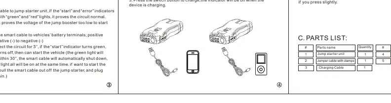
The device features a jump start socket, USB1 (QC) output, USB2 (5V/2A) output, 15V/5A output, LED display, switch button, and LED flash light. The package includes the jump starter unit, jumper cable with clamps, and a charging cable.
Jump Starting a 12V Vehicle
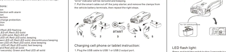
- Ensure the jump starter power is above 80%.
- Plug the jumper cable into the jump start socket.
- Connect the RED clamp to the vehicle's positive (+) terminal and the BLACK clamp to the negative (-) terminal.
- Check the smart cable indicators. If the 'start' indicator turns green, you may start the vehicle.
- Start the vehicle. If it fails, wait at least 30 seconds between attempts.
- Once started, remove the jumper cable from the jump starter and disconnect the clamps from the battery within 30 seconds.
Smart Cable Indicators
- Green and Red flashing: Detecting.
- Green LED off, Red LED solid: Low voltage.
- Green LED solid, Red LED off: Ready to start.
- Green LED off, Red LED solid, beeping: Short circuit.
- Green LED off, Red LED solid, discontinuous beeping: Reverse polarity.
- Green LED off, Red LED solid, slow beeping: Reverse charge.
- Green LED off, Red LED solid, fast beeping: Over-heating.
- Green and Red all solid: Over current or Timing protection (30 seconds).
Charging Devices
To charge mobile devices, plug the charging cable into a USB output port, select the appropriate connector, and press the switch button. The device will power off automatically when no load is detected or charging is complete.
LED Flashlight
Press and hold the switch button for 3 seconds to turn on the LED light. Press slightly to cycle through the 3 modes: illumination, strobe, and SOS.
Technical Specifications
- Start current: 650A
- Peak current: 1300A
- Input: 5V/2A
- Output: 5V/2A; QC 5V/9V/12V; 12V/5A; 15V/5A
- Operation temperature: -20°C to 60°C
- Full charging time: Approx. 6.5 hours
Safety Warnings
- Do not connect the two clamps together.
- Do not disassemble the unit.
- Do not immerse in water or expose to temperatures exceeding 70°C.
- Charge only at ambient temperatures between 0°C and 60°C.
Practical help
Common problems
No response when pressing the switch button
Low voltage protection is active. Plug the charging cable into the input port to recharge and activate the unit.
Vehicle will not start
Ensure the jump starter is charged to at least 80%. Check that the smart cable indicators show 'Ready to start' (Green LED solid). If it fails after 3 attempts, check the vehicle engine or circuit.
Smart cable beeping or showing red light
Check for short circuit, reverse polarity, or overheating. Disconnect and reconnect following the correct steps.
Before use
- Ensure the jump starter is charged to at least 80%.
- Verify the vehicle battery is 12V.
- Check that the smart cable is properly connected to the jump starter.
- Ensure the clamps are connected to the correct battery terminals (Red to +, Black to -).
Specs in practice
- Start current: 650A
- The standard current output for cranking the engine.
- Peak current: 1300A
- The maximum burst current the device can provide for a short duration.
- Operation temp: -20°C to 60°C
- The safe temperature range for operating the device.
Images and diagrams
- The product layout diagram identifies the location of the jump start socket, USB ports, and LED display.
- The smart cable connection diagram illustrates the correct sequence for attaching clamps to the vehicle battery.
Model compatibility
- Designed for 12V vehicles only.
- The 15V/5A output port is for 12V vehicle products or electronics.

Manual page author
David Miller
Documentation analyst
Organizes user manual content into clear summaries, with attention to model details, product context, and everyday usability.