Electronics / Audio
Behringer 2600-VCO Eurorack Module User Manual
Quick start guide for the Behringer 2600-VCO Eurorack module. Includes instructions for power connection, installation, control descriptions, and technical specifications.
Table of contents
Manual images
Click an image to enlargeQuick Start Guide
This guide provides essential information for setting up and using the Behringer 2600-VCO, a legendary analog VCO module designed for Eurorack systems. Ensure you follow all safety instructions and power connection procedures to avoid damaging the module.
Controls
The 2600-VCO features the following controls:
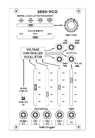
- Initial Oscillator Frequency: Selects the initial frequency of the VCO. Audio mode range: 10 Hz to 10 kHz; Low Frequency (LF) mode range: 0.03 Hz to 30 Hz.
- Fine Tune: Allows tuning the 2600 VCO to other instruments (range ±0.4 octaves).
- Pulse Width: Manual control over the pulse waveform width (10% to 90%).
- Outputs: Separate outputs for sine, triangle, sawtooth, and pulse waveforms.
- Keyboard CV Input: Accepts control voltages (0 V – 10 V) from a keyboard or MIDI/CV converter.
- FM Inputs and Levels: Inputs for frequency modulation of the VCO with attenuators.
- Pulse Width Modulation Input and Level: Input for external modulation of pulse width with attenuator.
- Keyboard On/Off Switch: Disables keyboard voltage, switching the VCO to Low Frequency mode.
Power Connection
The module includes a power cable for standard Eurorack systems. Follow these steps to connect:
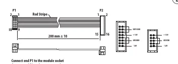
- Turn off the power supply or rack case and disconnect the power cable.
- Insert the 16-pin connector into the power supply or rack case socket. The connector is keyed to prevent incorrect insertion. If the socket is not keyed, ensure pin 1 (-12 V) aligns with the red stripe on the cable.
- Insert the 10-pin connector into the socket on the back of the module, ensuring correct orientation.
- Once both ends are securely attached, mount the module and turn on the power.
Installation
The module includes necessary screws for mounting in a Eurorack case.
- Connect the power cable before mounting the module.
- Align the module's mounting holes with the threaded rails or plates in your Eurorack case.
- Start by attaching the screws partially to allow for positioning adjustments.
- Once the module is correctly positioned, tighten the screws securely.
Technical Specifications
Inputs:
- Keyboard CV: 1 x 3.5 mm TS jack, DC coupled, 100 kΩ impedance.
- FM 1/2/3 CV: 3 x 3.5 mm TS jacks, DC coupled, 50 kΩ impedance.
- PWM CV: 1 x 3.5 mm TS jack, DC coupled, 75 kΩ impedance.
Outputs:
- TRI/SINE/SAW/PULSE: 4 x 3.5 mm TS jacks, DC coupled, 1 kΩ impedance.
Power & Physical:
- Power Supply: Eurorack.
- Current Draw: 140 mA (+12 V), 5 mA (-12 V).
- Dimensions (H x W x D): 129 x 81 x 42 mm (5.08 x 3.19 x 1.65").
- Rack Units: 16 HP.
- Weight: 0.15 kg (0.33 lbs).
Manufacturer information
Behringer
Practical help
Common problems
Module does not power on
Verify the power cable is connected correctly. Ensure the red stripe on the cable aligns with the -12 V pin on the power supply.
VCO not tracking correctly
Check that the Keyboard CV input is receiving a valid 0 V – 10 V signal and that the Keyboard On/Off switch is set correctly.
No sound output
Ensure the module is in the correct mode (Audio vs LF) and that the output jacks are properly connected to your signal chain.
Before use
- Ensure the Eurorack case power is turned off.
- Verify the power cable orientation (red stripe to -12 V).
- Check that the module fits the 16 HP space in your rack.
- Ensure all mounting screws are tightened after final positioning.
Images and diagrams
- The front panel diagram illustrates the layout of all inputs, outputs, and sliders for frequency, pulse width, and modulation.
- The power connection diagram shows the 16-pin to 10-pin cable orientation and pinout.
Model compatibility
- Requires a standard Eurorack power supply system.
- Compatible with 0 V to 10 V control voltage signals.

Manual page author
Emily Carter
User documentation editor
Prepares concise manual descriptions and highlights the most useful setup, operation, and maintenance information for readers.