Garden / Outdoor
Exploded View and Spare Parts Guide for Bosch GRT 18V-33 Cordless Grass Trimmer
A comprehensive technical guide for the Bosch GRT 18V-33 cordless grass trimmer, featuring detailed exploded view diagrams, torque specifications for assembly, and identification of key components and power accessories.
Table of contents
Manual images
Jump to the sectionQuick guide from the manual
This document serves as the official exploded view and spare parts reference for the Bosch GRT 18V-33 cordless grass trimmer (model number 3 600 HD0 0E0). It is intended for technicians and users performing maintenance or repairs. The guide provides a detailed breakdown of all internal and external components, along with critical torque specifications required for proper reassembly.
Exploded view and component identification
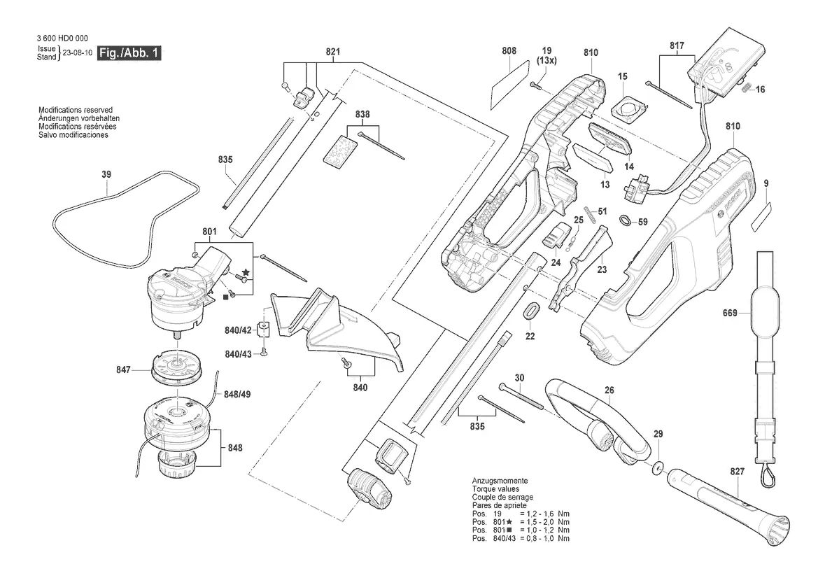
The manual provides a comprehensive visual breakdown of the trimmer's construction. Key assemblies include the motor housing, handle assembly, cutting head mechanism, and protective guard. Each part is numbered for identification, allowing for precise ordering of replacement components through authorized Bosch service channels.
Assembly and torque specifications
When reassembling the unit, it is critical to adhere to the specified torque values to ensure structural integrity and safe operation. Failure to use the correct torque may result in component damage or operational failure. The following torque values are specified:
- Pos. 19: 1.2 - 1.6 Nm
- Pos. 801 (star symbol): 1.5 - 2.0 Nm
- Pos. 801 (square symbol): 1.0 - 1.2 Nm
- Pos. 840/43: 0.8 - 1.0 Nm
Power accessories
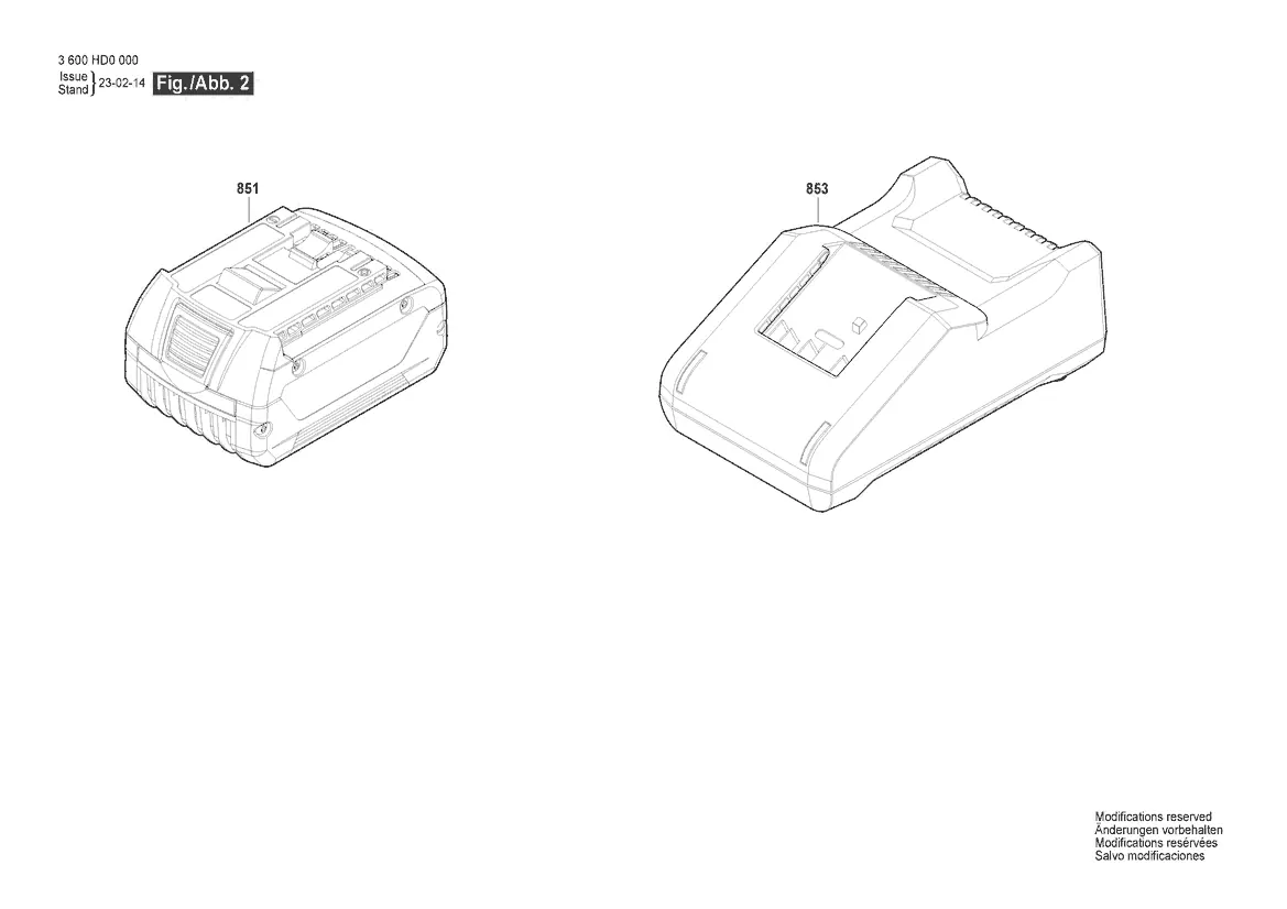
The document identifies the compatible battery pack (Pos. 851) and battery charger (Pos. 853) designed for use with the GRT 18V-33 system. Ensure only genuine Bosch power accessories are used to maintain safety and performance standards.
Service and support
For further technical assistance, spare parts inquiries, or service, please visit the official Bosch tool service website at https://www.boschtoolservice.com. The manufacturer reserves the right to make technical modifications to the product design.
Official resources from the manual
Manufacturer information
Bosch
Practical help
Common problems
Loose housing or handle components
Verify that all screws are tightened to the specified torque values (e.g., 1.2-1.6 Nm for Pos. 19).
Cutting head malfunction
Inspect the assembly of parts 847 and 848/49 as shown in the exploded view to ensure correct alignment.
Before use
- Ensure all screws are tightened to the manufacturer's specified torque.
- Verify that the protective guard (Pos. 840) is securely attached.
- Check that the battery pack (Pos. 851) is fully charged and compatible.
- Inspect the cutting line and head assembly for signs of wear or damage.
Specs in practice
- Torque values
- The specific rotational force required for fasteners to ensure the tool is assembled safely and securely.
- 3 600 HD0 0E0
- The specific machine identification number required when ordering spare parts.
Images and diagrams
- The exploded view (Fig. 1) illustrates the internal wiring, motor housing, and handle assembly.
- Fig. 2 provides a clear identification of the battery and charger units.
Model compatibility
- Use only genuine Bosch spare parts identified by the position numbers in the diagrams.
- The tool is designed for use with the 18V battery system indicated in the parts list.

Manual page author
Michael Turner
Technical manual editor
Reviews PDF manuals for structure, safety notes, and practical product details so readers can find the right information quickly.