HVAC / Thermostats & Controls
User Manual for Carrier 19XR/XRV Centrifugal Liquid Chiller
Comprehensive guide for the Carrier 19XR/XRV single-stage centrifugal liquid chiller. Includes technical specifications, control system features (SmartVu™), connectivity options, and physical dimensions.
Table of contents
Manual images
Click an image to enlargeKey Information and Overview
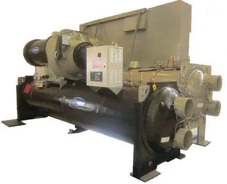
The Carrier 19XR/XRV is a high-efficiency, single-stage centrifugal liquid chiller designed for large-capacity water cooling applications. It features a hermetic compressor with aerodynamic impellers and tunnel diffusers. The unit is designed for stability, low noise, and modular construction, with a nominal cooling capacity ranging from 1000 to 3000 kW.
SmartVu™ Control System
The chiller is equipped with the Carrier® SmartVu™ control system, which provides comprehensive monitoring and control capabilities.
- Interface: Features a 10-inch color touchscreen that supports up to ten languages and displays real-time operating parameters.
- Intelligent Operation: Includes pre-start checks (oil temperature, condensation pressure, bearing temperature, etc.) and dynamic regulation algorithms to optimize efficiency.
- Diagnostics: The system includes fault diagnostics with alarm codes. It can perform pre-diagnostics for maintenance (e.g., oil and filter replacement alerts) and send automatic email notifications in case of alarms if connected to the internet.
- Connectivity: Supports BACnet or Modbus protocols for easy integration into building automation systems or i-Vu™/WebCTRL™ networks.
Carrier ABOUND Connectivity
The system supports the Carrier ABOUND platform, which utilizes cellular communication to transmit real-time operating data to the cloud.
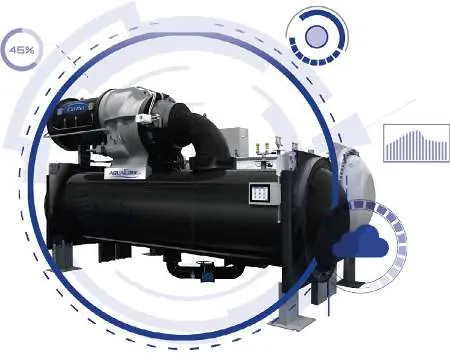
- IoT Integration: Provides continuous monitoring of equipment health and performance.
- Remote Diagnostics: Allows service technicians to access real-time data and maintenance history remotely, facilitating faster troubleshooting and repair.
- Analytics: Compares current performance against design specifications to provide actionable insights and preventive service solutions.
Options and Accessories
Various options are available to customize the chiller for specific applications:
- Variable Frequency Drives (VFD): Standard and high-efficiency options available.
- Motors: High-voltage motors (3000V to 11kV, 50Hz or 60Hz).
- Installation Aids: Anti-vibration springs, factory-installed starters, and delivery in multiple sections.
- Specialized Modules: Refrigerant leak detection sensors and hot gas bypass for low-load operation.
- Customization: Available for marine, oil and gas, and chemical industry applications.
Physical Specifications
The chillers are available in different chassis sizes (3, 4, and 5). Dimensions and weights vary based on the configuration. Users should refer to the physical characteristics table in the manual for precise length, width, height, and weight data (net and in-service) before installation.
Manufacturer information
Carrier Global Corporation
Practical help
Common problems
Alarm triggered on SmartVu™ screen
Access the alarm menu on the touchscreen to view the specific error code and consult the service documentation.
Communication failure with building automation system
Verify the BACnet or Modbus connection settings and ensure the i-Vu™ Link module is properly configured.
Maintenance required alert
The pre-diagnostic function indicates specific maintenance needs, such as replacing oil or filters.
Before use
- Verify oil temperature is within normal operating range.
- Check condensation pressure and bearing temperature.
- Ensure motor winding temperature is normal.
- Confirm the SmartVu™ system is powered and the touchscreen is responsive.
- Check that all isolation valves are in the correct position.
Specs in practice
- Cooling Capacity
- Nominal range of 1000-3000 kW.
- Control Protocol
- Supports BACnet or Modbus for building automation integration.
Images and diagrams
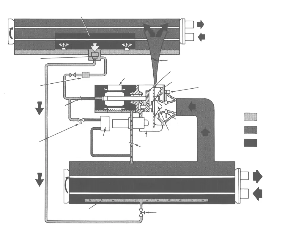
- The refrigeration cycle diagram illustrates the flow of refrigerant through the compressor, condenser, and evaporator, highlighting the oil pump, motor, and various valves.
Model compatibility
- Compatible with i-Vu™ building automation systems.
- Supports high-voltage motors (3000V, 3300V, 5500V, 6300V, 10kV, 11kV).

Manual page author
Emily Carter
User documentation editor
Prepares concise manual descriptions and highlights the most useful setup, operation, and maintenance information for readers.