HVAC / Thermostats & Controls
Operating Manual for Carrier Dry-Pic 09PE - 09VE Dry Cooler Controller
Quick guide and operating manual for the Carrier Dry-Pic 09PE and 09VE dry cooler controller. Includes setup, menu navigation, electrical connection diagrams, and parameter configuration.
Table of contents
Manual images
Click an image to enlargeQuick Start and Navigation
The Carrier Dry-Pic 09PE/09VE controller is managed via a front-panel interface with four navigation keys and an LCD screen. Upon startup, the screen displays the status menu. If no interaction occurs for one hour, the system reverts to the status menu.
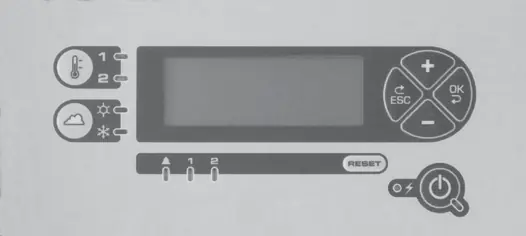
- ESC: Return to the previous menu level.
- OK: Select menu or parameter; confirm value.
- +/-: Navigate menus, parameters, or adjust values.
Device Description
The controller manages temperature regulation, fan stages, and communication with external systems (BMS). It supports various configurations, including flat or V-shaped battery setups, and single or dual-circuit systems.
Electrical Connections
The controller features multiple connection terminals (J2-J14) for sensors, fan control, and BMS communication. Ensure all wiring is performed according to the specific terminal layout provided in the manual. Use shielded cables for BUS communication and keep them separated from power lines (400V) by at least 30cm.
Operating Functions
- Regulation: Supports On/Off (cascading), speed variation (EC motors), and mixed regulation modes.
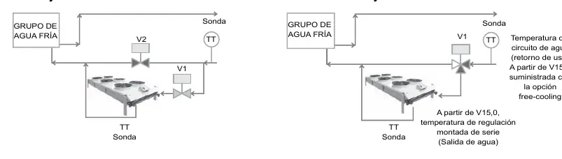
- Free-cooling: Optimizes cooling by comparing return water temperature with ambient air.
- Pulverization: Enhances cooling efficiency by spraying water; configurable based on water consumption or electrical optimization.
- Heating: Available in specific configurations to warm the fluid using ambient air.
Configuration and Parameters
Parameters are organized into menus (1-11). Menu 4 contains factory-locked settings, while Menu 5 allows for user adjustments. Key parameters include:
- A07: Regulation type selection.
- A111: Free-cooling activation.
- A113: Pulverization optimization mode.
- A114: Maximum fan speed threshold.
BMS Communication
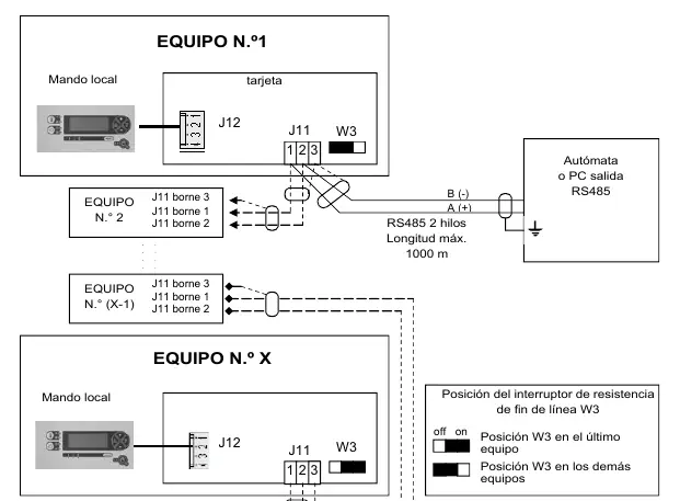
The controller supports RS485 (Modbus) and TCP communication. Ensure the W3 resistor is set correctly for the last device on the BUS. Communication status is indicated by D50 (receive) and D52 (transmit) LEDs.
Troubleshooting
The controller logs the last 9 faults. Common issues include sensor failures or fan stage errors. Use the 'Reset' key to clear faults after addressing the underlying cause.
Manufacturer information
Carrier Global Corporation
Practical help
Common problems
Communication error on BUS
Check wiring on J11/J10. Ensure the W3 resistor is set to 'on' only on the last device in the chain.
Fan stage failure
Check the specific fan stage alarm in the menu and verify the electrical connection for that stage.
Free-cooling not activating
Verify the temperature difference parameters (A117/A118) and ensure the ambient temperature sensor is correctly placed.
Before use
- Ensure power supply is 230V AC/50Hz.
- Verify all sensor connections (J7, J8) are secure.
- Check that the BUS cable is shielded and properly grounded.
- Confirm the correct configuration of parameters (A01-A10) for your specific hardware setup.
Images and diagrams
- Wiring diagrams (J3-J14) detail connections for fans, sensors, and BMS.
- Menu structure diagram illustrates navigation levels.
Model compatibility
- Compatible with V07+ software for RS485/TCP communication.
- Requires specific relay cards (ADD3) for remote visualization on dual-circuit systems.

Manual page author
David Miller
Documentation analyst
Organizes user manual content into clear summaries, with attention to model details, product context, and everyday usability.