Hvac / Heat Pumps
Installation Guide for Carrier 48/50V Package Rooftop Unit Accessory Roof Curbs
Comprehensive installation guide for Carrier 48/50V package rooftop unit accessory roof curbs. Includes assembly steps, bracket installation, gasketing, and flashing procedures.
Table of contents
Manual images
Jump to the sectionQuick guide from the manual
This document provides installation instructions for Carrier 48/50V accessory roof curbs. These curbs are shipped in a knockdown state and require assembly. Key steps include verifying parts against the provided tables, cutting and framing the roof opening, assembling the curb sides and supports, and ensuring a watertight seal using the provided gasket and field-supplied flashing materials.
Safety considerations
Installation of this accessory involves system pressures, electrical components, and elevated work locations. Only trained, qualified installers and service technicians should perform the installation. Always follow safety codes, wear appropriate safety glasses and work gloves, and exercise caution when handling the equipment.
Installation procedure
Before beginning, verify the curb part number matches the unit configuration using Table 1 and ensure all parts are present according to Tables 2-4. Check unit certified drawings for required service clearances and leveling tolerances.
- Cut the hole in the roof for cross openings, ensuring you do not cut out the entire area underneath the curb.
- Frame the roof opening to provide adequate structural support.
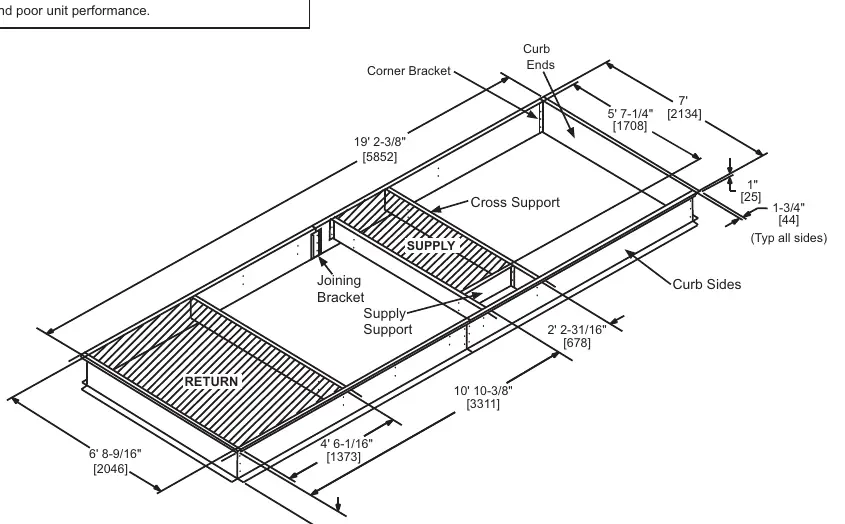
- Assemble the curb sides using the joining brackets and corner brackets.
- Attach the curb side assembly to the curb ends using corner brackets.
- Screw the cross supports and supply support in place.
- Ensure the curb is square by measuring equal distances across the corners. Once square, attach the curb to the building structure following all applicable codes.
Bracket assembly
The assembly process varies based on the bracket type:
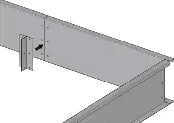
- Joining Bracket: Used to combine long curb sides and ends. Install on the inside of the curb, aligning with pre-punched holes. Secure with bolts from the outside and wood screws at the top.
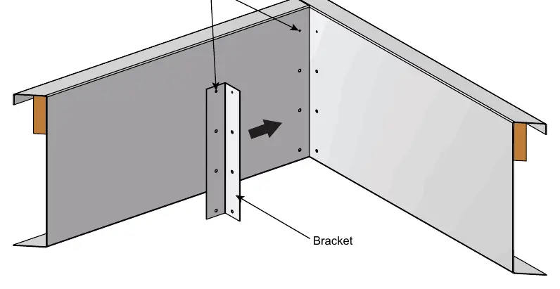
- Corner Bracket: Used to connect curb sides and ends. Place on the inside of the curb and secure with bolts from the outside.
- 90 Degree Joining Bracket: Used for specific long curb configurations. Install on the inside of the curb, aligning with pre-punched holes, and secure with bolts and wood screws.
Ductwork and flashing
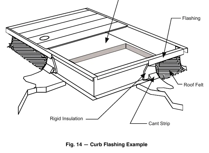
Ductwork must be installed prior to placing the Rooftop Unit (RTU) on the curb. Ensure the curb position does not interfere with supply and return ductwork clearances. The roof curb and unit must be sealed completely to prevent water or air leakages. Field-provided materials such as cant strips and counterflashing are required to ensure proper drainage and protection of the upper edge of the base flashing.
Applying the gasket material
The gasket is critical for water and air integrity. Improper installation can lead to leaks and poor unit performance.

- Clean the top surface of the curb thoroughly to remove dirt or contaminants.
- Lay out, measure, and cut the gasket as needed.
- Remove the adhesive paper backing and apply the gasket to the curb perimeter flanges and duct supports.
- Join the gasket strips together at the corners, ensuring a tight fit with no gaps.
- Avoid sliding the unit into position while it is resting on the curb to prevent damaging the gasket.
Manufacturer information
Carrier Global Corporation
Practical help
Common problems
Air leaks or water penetration
Ensure the gasket is applied without gaps at the corners and that the unit is not slid into position, which can damage the seal.
Structural instability
Ensure the curb is perfectly square by measuring equal distances across the corners before attaching it to the building structure.
Improper drainage
Ensure a cant strip is field-provided and installed to prevent sharp bends in roofing material and to aid in drainage.
Before use
- Verify curb part number matches unit configuration (Table 1).
- Verify all curb parts have been received (Tables 2-4).
- Check unit certified drawing for required service clearances.
- Ensure curb can be installed within leveling tolerances.
- Ensure all necessary field-supplied materials (cant strip, counterflashing, rigid insulation) are available.
Specs in practice
- Knockdown Curb
- The curb is shipped disassembled and must be assembled on-site using the provided brackets.
- Leveling Tolerances
- Specific slope requirements for the unit to ensure proper operation; refer to Fig 1-9 for acceptable slope.
Images and diagrams
- Figures 1-9: Provide assembly diagrams for specific curb models, showing bracket locations and cross support placement.
- Figures 10-12: Detail the installation of joining, corner, and 90-degree brackets.
- Figure 14: Illustrates the proper flashing technique, including the placement of the cant strip, roofing felt, and counterflashing.
Model compatibility
- Curb usage is specific to the 48/50V unit tonnage and chassis type (Standard, Extended, Compact).
- Refer to Table 1 to match the specific Part No. with the correct 48V or 50V unit configuration.

Manual page author
Michael Turner
Technical manual editor
Reviews PDF manuals for structure, safety notes, and practical product details so readers can find the right information quickly.