HVAC / Evaporative Coolers
User Manual for Champion Industrial/Commercial Evaporative Cooler
Comprehensive user guide for Champion industrial and commercial evaporative coolers. Includes detailed instructions on installation, electrical wiring, water connection, maintenance, troubleshooting, and parts specifications for models...
Table of contents
Manual images
Click an image to enlargeQuick guide from the manual
This manual provides installation, operation, and maintenance instructions for Champion industrial and commercial evaporative coolers. Before beginning any installation or maintenance, always disconnect all electrical service to the unit. Ensure the mounting surface is strong enough to support the operating weight of the cooler. Proper grounding is required for safety. For efficient cooling, ensure adequate exhaust (at least 2 square feet of opening per 1000 CFM) and pre-wet the pads by running the pump for a few minutes before starting the blower.
Installation
Ductwork: Ensure ducts are sized correctly according to the general specification table. For down discharge units, the duct must go inside the opening. Side discharge units have a 1-inch flange; size ducts to fit over this flange.
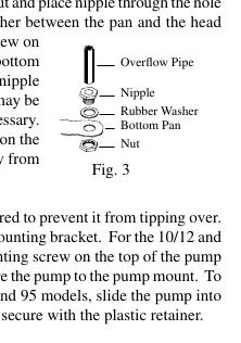
Water Connection: Install the overflow assembly by placing the nipple through the pan with the rubber washer between the pan and the nipple head. Secure the pump to the mounting bracket to prevent tipping. Connect a 3/8 inch water supply line to the float valve. Do not use water from a water softener.
Motor and Electrical: Mount the motor using the provided carriage bolts and adjustable channels. Align the motor pulley with the blower pulley. Electrical connections must be performed by a qualified electrician in accordance with local codes. Ensure the cooler is properly grounded.
Maintenance
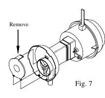
Spring Start-Up: Check belt tension and readjust if necessary. Oil blower bearings and cooler motor (if equipped with oil lines) with a few drops of non-detergent 20/30 weight oil once a year. Replace pads at the beginning and mid-season for maximum efficiency. Clean the pump and check for blockages.
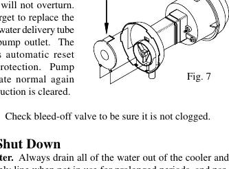
Winter Shut Down: Always drain all water from the cooler and water supply line. Disconnect the water line from both the unit and the supply to prevent freezing. Disconnect the power supply if the unit will not be used for extended periods. Covering the unit is recommended.
Troubleshooting
If the unit fails to start, check for blown fuses, tripped breakers, or loose belts. If air delivery is inadequate, check for insufficient exhaust, loose belts, or clogged pads. If there is a musty odor, drain the pan, clean the pads, and check the water distribution system.
Manufacturer information
Champion Power Equipment
Practical help
Common problems
Failure to start or no air delivery
Check electrical power, fuses, and circuit breakers. Inspect belt tension and ensure the motor is not overheated or locked.
Inadequate air delivery
Ensure there is sufficient air exhaust in the building. Check belt tension and clean clogged pads or water distribution system.
Musty or unpleasant odor
Drain the pan and clean the pads. Ensure the water distribution system is clean and the pump is working properly.
Motor cycles on and off
Check for low voltage, excessive belt tension, or dry bearings. Ensure the motor pulley diameter is not causing an overload.
Before use
- Ensure the mounting surface can support the operating weight of the cooler.
- Disconnect all electrical service before beginning installation.
- Verify the cooler is connected to the proper line current, voltage, and cycle.
- Ensure the cooler cabinet is properly grounded.
- Check that all bolts are securely tightened before starting.
- Pre-wet pads by running the pump for a few minutes before starting the blower.
Specs in practice
- CFM (Cubic Feet per Minute)
- Determines the required exhaust opening size (at least 2 sq ft per 1000 CFM).
- Static Pressure
- Used in motor specification tables to determine the correct pulley and motor configuration.
- HP (Horsepower)
- Indicates the motor power capacity; must match the unit requirements.
Images and diagrams
- Fig 1 & 2: Motor and pulley installation and alignment.
- Fig 3: Water overflow assembly and drain connection.
- Fig 4: Float valve installation.
- Fig 5: Pulley adjustment for amperage control.
- Fig 6: Belt tensioning (3 lb force for 3/4 inch deflection).
Model compatibility
- Do not use water supplied from a water softener.
- Curbs are not provided; the installer is responsible for providing support.
- Electrical hookup must be performed by a qualified electrician.
- Motors without oil lines are lifetime oiled at the factory.

Manual page author
David Miller
Documentation analyst
Organizes user manual content into clear summaries, with attention to model details, product context, and everyday usability.