Tools / Chemical Sprayers
User Manual for Chapin 22180XP Industrial Poly Concrete Sprayer
Quick guide for the Chapin 22180XP Industrial Poly Concrete Sprayer. Learn how to assemble, pressurize, spray, and maintain your sprayer safely.
Quick answers from the manual
Quick answer
- To operate the Chapin 22180XP, assemble the hose to the tank, fill with solution, pump until resistance is felt, and use the handle to spray. Always release pressure using the relief valve before opening the tank. p. 1
Key actions
- Release pressure p. 1
- Clean the sprayer p. 1
First start
- Assemble hose to tank p. 1
Show 3 more answers Show less
Problems and fixes
Hose deterioration
Replace hose before using with original manufacturer's parts.
p. 1Maintenance and reset
- Oil the pump p. 1
Where to find it in the PDF
- Assembly and Operation p. 1
Table of contents
Manual images
Click an image to enlargeQuick guide from the manual
This sprayer is designed for industrial use. Safety is critical: never leave a pressurized sprayer in the hot sun, as heat can cause pressure build-up and explosion. Always wear protective gear (goggles, gloves, long sleeves, long pants, and full foot protection) when spraying. Never use flammable, caustic, acidic, chlorine, bleach, or other corrosive solutions that produce heat, pressure, or gas.
Assembly
Hose to Tank:
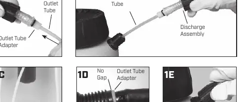
- Ensure the white outlet tube is attached to the outlet tube adapter (Fig 1A).
- Insert the outlet tube portion of the discharge assembly into the tank adapter (Fig 1B).
- Align the tab with the notches on the tank adapter (Fig 1D).
- Firmly tighten the retaining nut to the tank adapter (Fig 1E).
Nozzle:
- Attach the nozzle to the shut-off handle or extension wand (Fig 2A, 2B).
Pre-Use Check
Before filling, perform these checks to ensure safety:
- Check the tightness of the hose nut.
- Inspect the hose for cracks, softness, or brittleness. Replace if found.
- Inspect the tank interior and exterior for signs of deterioration.
- Test the unit with water only first to check for leaks.
- Ensure the nozzle is not clogged.
Filling and Pressurizing
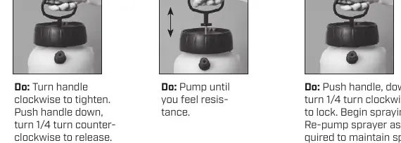
- Filling: Turn the pump handle counterclockwise to remove the pump. Fill the tank to the proper gallon marker. Do not overfill.
- Pressurizing: Replace the pump and tighten securely. Turn the handle clockwise to tighten. Pump until you feel resistance (Fig 5B).
- Spraying: Push the handle down and turn 1/4 turn clockwise to lock. Begin spraying. Re-pump as required to maintain spray force.
- Fatigue-Free Spraying: For constant spraying, push down on the shut-off handle and move the locking mechanism away from you. To release, squeeze the handle and move the locking mechanism back.
Pressure Release
Always release pressure before opening the tank:
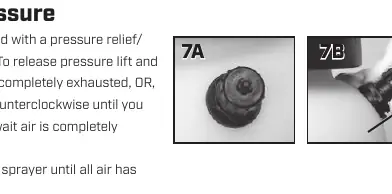
- Lift and hold the pressure relief valve cap until air is completely exhausted (Fig 7A).
- Alternatively, turn the valve slowly counterclockwise until air stops escaping (Fig 7B).
- Stay away from the sprayer until all air has escaped.
Care and Maintenance
- Cleaning: Follow chemical manufacturer's instructions. Rinse thoroughly with the recommended solvent. Run solvent through the discharge assembly.
- Storage: Store the tank upside down with the pump removed in a warm, dry location.
- Oiling: Periodically oil the pump by dropping 10-12 drops of light oil down the pump rod through the opening in the cover.
Practical help
Common problems
Sprayer not holding pressure
Check that the pump is tightened securely, the pressure relief valve is closed, and the hose nut is tight.
Hose leaking or damaged
Inspect for cracks or brittleness. Replace immediately with original manufacturer's parts.
Nozzle clogged
Remove the nozzle and clean it. If damage is visible, replace the part.
Before use
- Check hose nut tightness
- Inspect hose for deterioration, cracks, or brittleness
- Inspect tank for signs of body or bottom deterioration
- Test with water only (10-20 pump strokes) to check for leaks
- Ensure nozzle is not clogged
Show more Show less
Specs in practice
- Pressure Relief Valve
- Safety mechanism to exhaust air pressure before opening the tank.
- Fatigue-Free Spraying
- A locking mechanism on the handle that allows continuous spraying without holding the lever down.
Images and diagrams
- Fig 1A-1E: Step-by-step hose to tank assembly.
- Fig 5A-5C: Sequence for pressurizing and locking the pump.
- Fig 7A-7B: Methods for operating the pressure relief valve.
Model compatibility
- Use only original manufacturer's parts for replacements.
- Do not use flammable, caustic, acidic, chlorine, or bleach solutions.

Manual page author
David Miller
Documentation analyst