Electronics / Networking
Troubleshooting Guide for Cisco NCS 1010
A comprehensive troubleshooting guide for the Cisco NCS 1010, covering infrastructure, data path, and optical application alarms, along with general network failure resolution procedures.
Quick answers from the manual
Quick answer
- This guide provides troubleshooting procedures for infrastructure, data path, and optical application alarms on the Cisco NCS 1010. It includes steps to clear specific alarms and resolve general network failures like L/C band failures and span failures. p. 1, 33, 47, 63
Key actions
- Collect diagnostic logs p. 14
- Check active alarms p. 14, 76
Problems and fixes
EQUIPMENT_FAILURE
Collect logs, check active alarms, examine ambient temperature, voltage, current, and power supply.
p. 14Show 2 more answers Show less
Maintenance and reset
- Cold reload of Line Card p. 14, 15
Where to find it in the PDF
- Infrastructure Alarms p. 1, 11
- Data Path Alarms p. 33, 43
- Optical Application Alarms p. 47, 57
- General Troubleshooting p. 63, 73
Table of contents
Manual images
Click an image to enlargeTroubleshooting Guide Overview
This guide provides detailed procedures for identifying and resolving common alarms and network failures encountered when operating the Cisco NCS 1010 chassis. It is divided into sections covering infrastructure, data path, and optical application alarms, as well as general network troubleshooting.
Infrastructure Alarms
Infrastructure alarms typically relate to hardware health, power, and system initialization. Common alarms include:
- LICENSE-COMM-FAIL: Indicates inability to communicate with the Cisco license cloud server. Restore connectivity to clear.
- FAN FAIL / FAN SPEED SENSOR: Indicates fan tray issues. Replace faulty fans or fan trays.
- EQUIPMENT_FAILURE: Raised when components like optical modules, line cards, or FPGAs fail. Collect logs using show tech-support and verify ambient temperature and power supply.
- [Low | High] Voltage: Indicates power source issues. Verify voltage levels; alarms clear automatically when within operating range.
Data Path Alarms
Data path alarms often relate to signal integrity and amplifier performance. Key procedures include:
- CHANNEL-NOISE-LOADED: Clears automatically when the original traffic channel is restored.
- EGRESS/INGRESS-AMPLI-GAIN-HIGH/LOW: Adjust gain settings using controller ots egress-ampli-gain or ingress-ampli-gain commands.
- RX-LOS-P: Indicates loss of signal payload. Check fiber connections, ensure cables are properly inserted, or adjust threshold settings.
Optical Application Alarms
These alarms relate to optical performance and topology discovery:
- APC-BLOCKED-RX/TX: Indicates the Automatic Power Control (APC) domain is down. Resolve fiber cuts or network events to clear.
- OTDR-ABS-ATTENUATION-EXCEEDED: Indicates attenuation events exceeding thresholds. Check fiber scan results.
- RAMAN-TUNE-FAILED: Often caused by high back reflection. Clean fiber and ports to resolve.
General Troubleshooting
This section covers complex network failures:
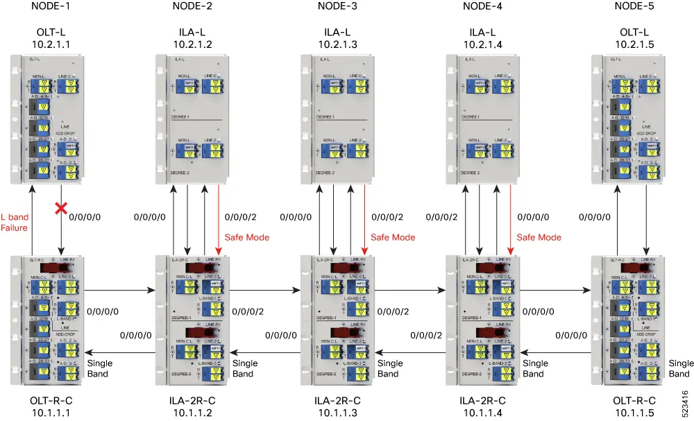
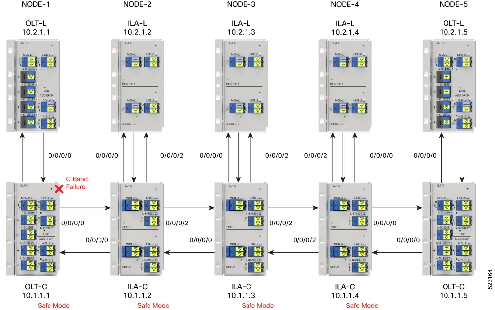
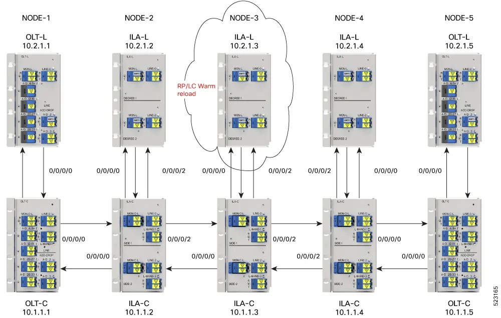
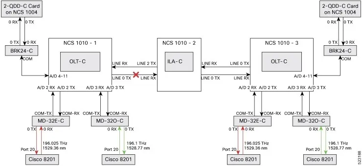
- L/C Band Failures: Use show olc band-status and show olc apc to identify connectivity issues between manager and agent nodes.
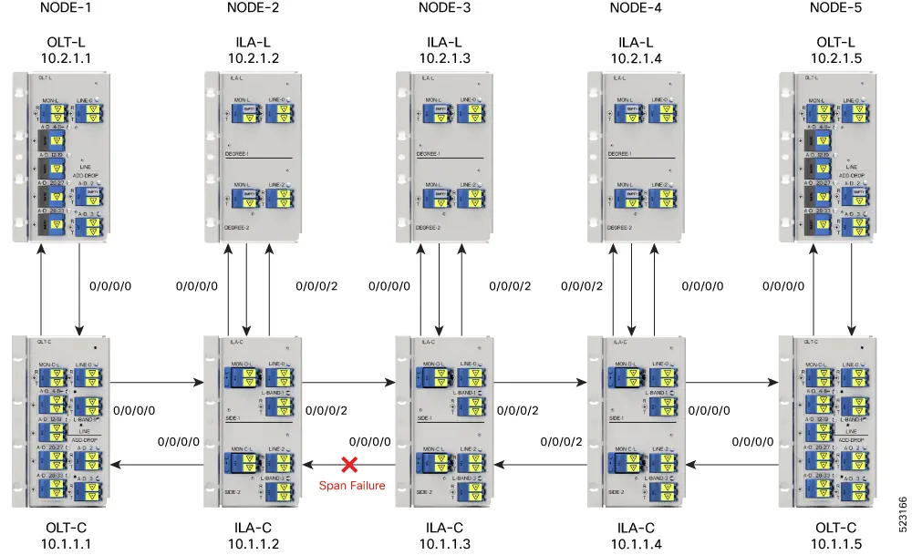
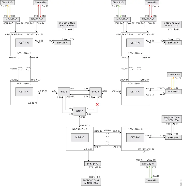
- Span Failures: Often indicated by Loss of Signal or Loss of Continuity alarms. Inspect fiber for damage and verify span length configurations.
- Client-Side Failures: Typically caused by fiber cuts. Check for LOS-P alarms at the AD port controller.
- Connection Verification Failures: Errors like Tone Generation Already In Progress or Invalid Pattern occur during configuration. Ensure correct tone-pattern and frequency values are set.
Manufacturer information
Cisco Systems, Inc.
Practical help
Common problems
LICENSE-COMM-FAIL
Restore communication with the Cisco cloud license server.
FAN FAIL
Replace the faulty fan in the chassis.
EQUIPMENT_FAILURE
Collect logs using 'show tech-support', check active alarms, and verify ambient temperature/voltage.
RX-LOS-P
Check fiber connection, ensure cable is properly inserted, or adjust threshold settings.
Before use
- Verify all fan trays are operational.
- Ensure ambient temperature is within recommended range.
- Check that all fiber connections are clean and secure.
- Verify power supply voltage is within operating range.
Show more Show less
Images and diagrams
- Diagrams illustrate fiber cut scenarios at AD ports, Line OTS controllers, and between passive devices to help identify physical layer failures.
- Visuals show L-band and C-band failure examples to assist in network topology troubleshooting.
Model compatibility
- Ensure all line cards and modules are compatible with the current configuration.

Manual page author
David Miller
Documentation analyst