Home Appliances / Fans
Commercial Electric SPT-1 Foot Pedal Switch User Guide
Quick guide for installing or replacing the Commercial Electric SPT-1 Foot Pedal Switch. Includes wiring instructions, compatibility requirements for 18AWG SPT-1 or SPT-2 wire, and troubleshooting for wire removal.
Table of contents
Quick guide from the manual
This document provides instructions for installing or replacing a foot pedal switch on a light fixture. Always ensure the power supply is turned off before beginning any installation work. This switch is compatible with 18AWG SPT-1 or SPT-2 wire.
Installation Instructions
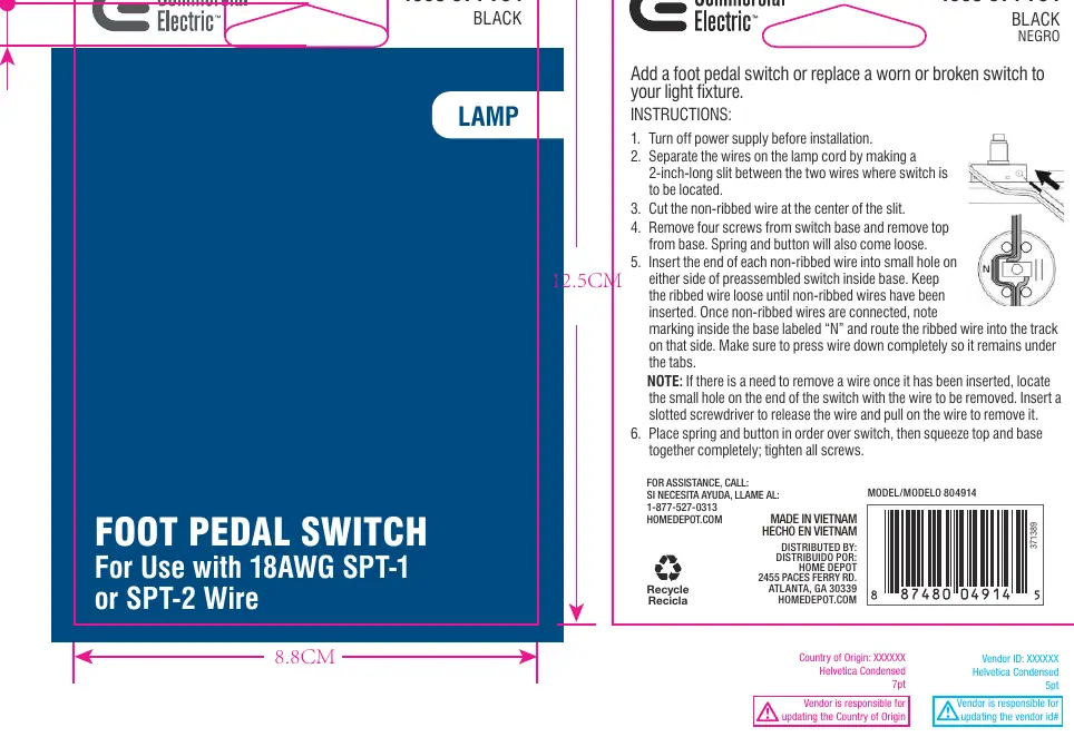
- Turn off the power supply before installation.
- Separate the wires on the lamp cord by making a 2-inch-long slit between the two wires where the switch is to be located.
- Cut the non-ribbed wire at the center of the slit.
- Remove the four screws from the switch base and remove the top from the base. The spring and button will also come loose.
- Insert the end of each non-ribbed wire into the small hole on either side of the preassembled switch inside the base. Keep the ribbed wire loose until the non-ribbed wires have been inserted.
- Once the non-ribbed wires are connected, note the marking inside the base labeled “N” and route the ribbed wire into the track on that side. Ensure the wire is pressed down completely so it remains under the tabs.
- Place the spring and button in order over the switch, then squeeze the top and base together completely and tighten all screws.
Wire Removal
If you need to remove a wire after it has been inserted, locate the small hole on the end of the switch with the wire to be removed. Insert a slotted screwdriver to release the wire and pull on the wire to remove it.
Contact Information
For assistance, call 1-877-527-0313 or visit HOMEDEPOT.COM.
Official resources from the manual
Manufacturer information
Commercial Electric
Practical help
Common problems
Need to remove a wire after insertion
Locate the small hole on the end of the switch corresponding to the wire, insert a slotted screwdriver to release the wire, and pull it out.
Switch components loose during assembly
Ensure the spring and button are placed in the correct order before squeezing the top and base together and tightening all four screws.
Before use
- Turn off the power supply
- Verify wire is 18AWG SPT-1 or SPT-2
- Prepare a 2-inch slit in the lamp cord
- Have a slotted screwdriver ready
Specs in practice
- 18AWG SPT-1 or SPT-2
- The specific gauge and type of lamp cord wire compatible with this switch.
Images and diagrams
- The diagram illustrates the wiring path, showing where to route the ribbed wire (marked 'N') and where to insert the non-ribbed wires into the switch base.
Model compatibility
- Designed for use with 18AWG SPT-1 or SPT-2 wire only.

Manual page author
David Miller
Documentation analyst
Organizes user manual content into clear summaries, with attention to model details, product context, and everyday usability.