Furniture / Home Furnishing
Cooper OSW-U 120-277V Wall Switch Ultrasonic Occupancy Sensor User Guide
Quick guide for the Cooper OSW-U ultrasonic occupancy sensor, covering installation, wiring diagrams, operating modes, and technical specifications.
Table of contents
Quick guide from the manual
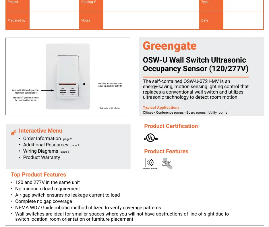
The Cooper OSW-U is a self-contained ultrasonic occupancy sensor designed to replace standard wall switches. It uses ultrasonic technology to detect motion in rooms such as offices, conference rooms, and utility areas. The device supports both 120V and 277V circuits and features an air-gap switch to ensure no leakage current to the load.
Operating modes
The sensor offers two primary operating modes, which can be configured via the override jumper:
- Automatic On Mode: Lights turn on automatically when motion is detected.
- Manual On Mode: Lights must be turned on by pressing the touchplate at the top of the switch.
In both modes, the lights turn off automatically after a programmed time delay (adjustable from 30 seconds to 15 minutes) once the room is vacated.
Installation and wiring
The sensor is designed to fit into a standard 3.5-inch deep back box. It requires a neutral wire connection. The manual provides specific wiring diagrams for:
- Single-Pole Switching: Standard connection for a single sensor controlling a load.
- 3-Way Switching: Connection for two sensors controlling the same load. Note: In 3-way applications, do not exceed the load ratings of a single switch.
Coverage and field of view
The OSW-U series provides a 180-degree coverage range. The maximum coverage area is approximately 500 sq. ft., with a minor motion coverage area of approximately 300 sq. ft. Coverage may vary based on room shape and obstructions.
Technical specifications
- Voltage: 120/277 VAC, 60 Hz
- Operating Temperature: 60°F to 80°F (15°C to 26°C)
- Humidity: Less than 95%, non-condensing
- Load Ratings (120V): Incandescent/Tungsten up to 800W, Motor load 1/4HP
- Load Ratings (277V): Fluorescent/Magnetic Ballast up to 1200W, Motor load 1/4HP
Practical help
Common problems
Lights not turning on automatically
Check if the unit is set to 'Manual On' mode (switch set to 'M'). If so, you must press the touchplate to turn the lights on.
Sensor coverage is insufficient
Ensure the sensor is not obstructed by furniture or room partitions, as ultrasonic technology relies on line-of-sight and acoustic wave reflection.
Exceeding load ratings in 3-way applications
Do not double the load rating when using two sensors in a 3-way configuration; adhere to the single switch load limits.
Before use
- Verify the supply voltage is 120V or 277V.
- Ensure a neutral wire is available in the wall box.
- Confirm the back box is at least 3.5 inches deep.
- Check that the room environment is within 60°F - 80°F.
- Ensure the load type (Incandescent, Fluorescent, or Magnetic Ballast) is compatible.
Specs in practice
- Air-gap switch
- A physical disconnect that ensures zero leakage current to the load when the switch is off.
- Ultrasonic technology
- Uses inaudible sound waves to detect motion; it does not respond to audible noise.
Images and diagrams
- The wiring diagrams show connections for Hot, Neutral, Ground, and Load.
- The 3-way diagram illustrates how to connect two sensors to a single load using traveler wires.
Model compatibility
- Compatible with magnetic ballasts.
- Not for outdoor use.
- Wallplate is not included with the unit.

Manual page author
Michael Turner
Technical manual editor
Reviews PDF manuals for structure, safety notes, and practical product details so readers can find the right information quickly.