Lighting / Controllers & Dimmers
User Manual for Greengate OSW-U-0721-MV Ultrasonic Occupancy Sensor
Quick guide for the Greengate OSW-U-0721-MV ultrasonic occupancy sensor. Includes wiring diagrams for single-pole and 3-way setups, installation tips, and configuration settings.
Table of contents
Manual images
Click an image to enlargeQuick Guide
The Greengate OSW-U-0721-MV is an ultrasonic occupancy sensor designed to replace a conventional wall switch. It uses ultrasonic technology to detect motion in a room, providing automatic lighting control. The unit features an air-gap switch to ensure no leakage current to the load when off.
Installation and Wiring
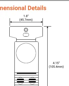
The sensor requires a standard 3.5-inch deep back box for installation. Ensure power is disconnected before beginning any wiring work.
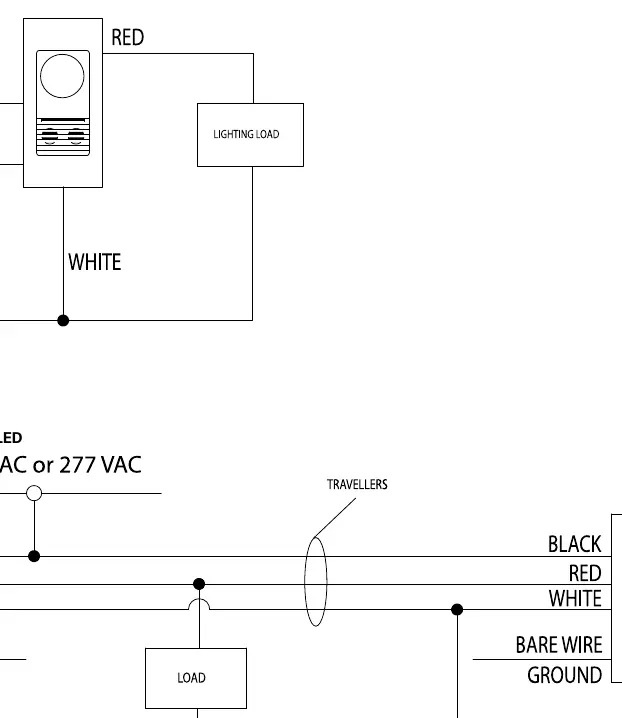
Single-Pole Wiring
- Connect the Hot wire (120/277V) to the sensor.
- Connect the Neutral wire to the sensor and the lighting load.
- Connect the Load wire from the sensor to the lighting load.
- Connect the Ground/Bare wire to the sensor ground.
3-Way Wiring
- Requires traveler wires between the two switches.
- Ensure the load ratings are not exceeded; load ratings cannot be doubled in 3-way applications.
Configuration and Controls
The sensor includes an override jumper and adjustment dials located on the front of the unit.
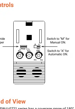
- Operating Modes: Switch to 'M' for Manual ON mode (lights must be turned on by pressing the touchplate). Switch to 'A' for Automatic ON mode (lights turn on automatically when motion is detected).
- Time Delay: Adjustable from 15 seconds to 15 minutes.
- Manual Override: The manual Off pushbutton can be used in either mode to turn lights off.
Technical Specifications
- Voltage: 120/277 VAC, 60 Hz.
- Coverage: 180 degrees, up to 500 sq. ft.
- Operating Temperature: 60°F to 80°F (15°C to 26°C).
- Load Ratings (120V): Incandescent/Tungsten up to 800W, Motor Load 1/4HP.
- Load Ratings (277V): Fluorescent/Magnetic Ballast up to 1200W, Motor Load 1/4HP.
- Compatibility: Compatible with magnetic ballasts.
Practical help
Common problems
Lights not turning on automatically
Ensure the unit is set to 'A' (Automatic ON) mode. Check for line-of-sight obstructions or if the sensor is facing a corridor.
False activations
Ensure the sensor is not positioned where it can detect motion from adjacent corridors or high-traffic areas.
Before use
- Verify the supply voltage is 120V or 277V.
- Ensure a standard 3.5-inch deep back box is available.
- Confirm the lighting load type (Incandescent, Fluorescent, or Magnetic Ballast).
- Check that the installation location allows for clear line-of-sight coverage.
- Ensure the wallplate is available (not included).
Specs in practice
- Coverage Area
- Maximum 500 sq. ft. with 180-degree field of view.
- Operating Temperature
- Must be installed in environments between 60°F and 80°F.
Images and diagrams
- Single-Pole Diagram: Shows direct connection of Hot, Neutral, Ground, and Load wires.
- 3-Way Diagram: Illustrates the use of traveler wires to connect two switches to a single load.
Model compatibility
- Compatible with magnetic ballasts.
- Not for use with electronic ballasts unless specified.
- Fits standard 3.5-inch deep back boxes.

Manual page author
Michael Turner
Technical manual editor
Reviews PDF manuals for structure, safety notes, and practical product details so readers can find the right information quickly.