Smart Home / Sensors Buttons
Installation Guide for CP Electronics EBDHS-AD PIR Presence/Absence Detector
A comprehensive installation and configuration guide for the CP Electronics EBDHS-AD 1-10V Dimming PIR Presence/Absence Detector. This guide covers mounting, wiring, detection patterns, masking shield application, and operational settings.
Table of contents
Manual images
Click an image to enlargeQuick guide from the manual
The EBDHS-AD is a PIR presence/absence detector designed for flush ceiling mounting. It supports 1-10V dimming and can be configured for either presence detection (automatic on/off) or absence detection (manual on, automatic off). The unit is shipped in presence detection mode by default. To switch to absence detection, press the external switch 5 times within the first minute of power-up; the LED will turn red for 30 seconds to confirm.
Installation
The device is designed for flush ceiling mounting. Follow these steps for installation:
- Cut a 64mm diameter hole in the ceiling.
- Ensure the sensor is not located within 1m of any lighting, forced air heating, or ventilation.
- Avoid locations where direct sunlight might enter the sensor.
- Do not mount on unstable or vibrating surfaces.
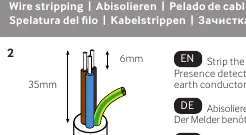
- Strip wires as shown in the manual (the detector does not require an earth conductor).
- Connect the wires according to the wiring diagram on page 3.
- Bend the springs up and push the detector through the hole in the ceiling. The springs will snap back to hold the device in place.
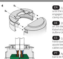
- Tighten the cable clamp screws until the clamp bar engages against the cable. The clamp must only grip the outer sheath.
Wiring
The manual provides diagrams for two main configurations:
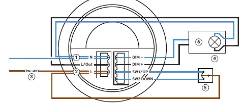
- Single channel dimming: Switches the luminaire with occupancy and maintains illuminance. Dims and switches using an optional centre-biased retractive switch.
- Single channel switching: Switches channel 1 only with occupancy. No dimming output.
Detection patterns
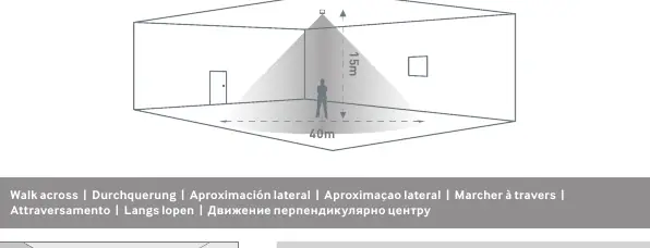
The detection range varies based on mounting height. At a 15m height, the range diameter is 40m (walk across) or 30m (walk towards). At a 3m height, the range diameter is 9m (walk across) or 8m (walk towards). The sensor head features 4 alignment marks corresponding to the 4 outer passive infrared sensors to help align with aisles and corridors.
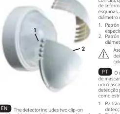
Masking shields
Two clip-on masking shields are included to enable precise masking of the detection shape for aisles and corners, or to narrow the detection diameter. Ensure all IR programming is completed before affixing the shields. Trim the masks laterally for aisles or along radial lines to narrow the detection diameter.
Technical data
- Supply voltage: 230 VAC +/- 10%
- Frequency: 50Hz
- Max load: 10A
- Time out range: 10 seconds to 99 minutes
- Working temperature: -10 to 35ºC
- Humidity: 5 to 95% non-condensing
- IP rating: 40
Practical help
Common problems
Load does not switch off automatically
Ensure the unit is not in presence mode if you require absence detection. Check for movement or heat sources within the detection zone.
Detection area is too large
Use the provided clip-on masking shields to narrow the detection diameter or mask specific areas like aisles.
Sensor not detecting movement
Ensure the sensor is not installed within 1m of lighting, forced air heating, or ventilation, and that it is not exposed to direct sunlight.
Before use
- Ensure power is disconnected before installation.
- Cut a 64mm diameter hole in the ceiling.
- Verify wiring against the diagram on page 3.
- Ensure the sensor is not near direct sunlight or ventilation.
- Confirm the desired detection mode (Presence vs Absence).
Specs in practice
- 1-10V Dimming
- Allows the sensor to control the light level of compatible dimmable ballasts.
- Presence Detection
- The unit automatically switches the load on when movement is detected and off when the area is vacant.
- Absence Detection
- The unit requires a manual switch to turn the load on, but automatically turns it off when the area is vacant.
Images and diagrams
- Wiring diagram shows connections for Neutral, Live, Load, and optional retractive switch.
- Detection pattern diagrams illustrate coverage based on mounting height (3m to 15m).
Model compatibility
- Requires 230V AC supply.
- Compatible with optional UHS5 or UNLCDHS handsets for configuration.

Manual page author
Michael Turner
Technical manual editor
Reviews PDF manuals for structure, safety notes, and practical product details so readers can find the right information quickly.