Smart Home / Sensors Buttons
User Manual for Sunricher SR-IG9030B-PIR-10AD Ceiling Mounted PIR Sensor
Quick guide for the Sunricher SR-IG9030B-PIR-10AD ceiling-mounted PIR sensor. Includes installation instructions, wiring diagrams, lens configuration, and detection pattern settings.
Table of contents
Manual images
Click an image to enlargeQuick guide from the manual
The Sunricher SR-IG9030B-PIR-10AD is a ceiling-mounted PIR sensor designed for DALI lighting control. Before installation, ensure the power is disconnected. The device comes with a pre-mounted low-bay lens and an optional high-bay lens. Proper placement is critical to avoid false alarms; keep the sensor away from heat sources, direct sunlight, and moving objects like fans or large plants.
Product Overview
This sensor acts as an INGY to DALI controller, utilizing a Wirepas mesh network for extended control distance. It features a 10A relay, magnetic reset functionality, and is rated IP20 for indoor use. It supports kinetic energy switches and EnOcean switches (EWSSB and EWSDB).
Installation and Wiring
Wiring Connections:
- L (Input): Black, 18 AWG
- N (Input): White, 18 AWG
- L' (Output): Red, 18 AWG
- DALI+ (Output): Yellow, 22 AWG
- DALI- (Output): Blue, 22 AWG
Ensure wire strip length is 10mm. The built-in 80mA DALI BUS output supports a minimum of 40 DALI control gears. Do not install with power applied to the device.
Lens Configuration
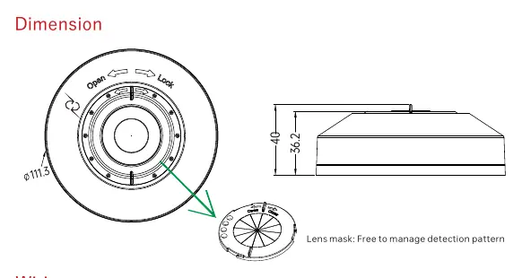
The sensor includes two lens types to suit different mounting heights:
- Low-bay lens (Default): Suitable for heights up to 3m.
- High-bay lens: Suitable for heights up to 12m.
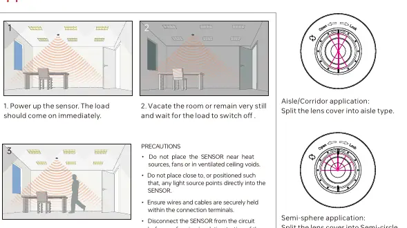
You can further customize the detection pattern using the provided lens mask to create Aisle/Corridor or Semi-circle detection patterns.
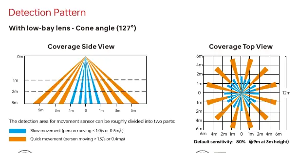
Detection Patterns
The detection area depends on the lens used and the installation height. The sensor distinguishes between slow movement (<0.3m/s) and quick movement (>0.4m/s). Performance may vary based on site conditions such as temperature, humidity, and blind areas.
Installation Precautions
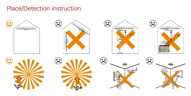
- Avoid areas with frequent temperature changes (air conditioners, fans, refrigerators, ovens).
- Do not face glass doors or windows directly to avoid strong light interference.
- Avoid installing opposite large, constantly moving objects.
- Ensure the sensor is not obstructed by furniture, screens, or large potted plants.
- Do not expose the device to moisture.
Technical Specifications
- Operating Voltage: 100-277VAC 50/60Hz
- Relay Capacity: Resistive: 10A, Capacitive: 8A, Inductive: 7A
- Stand-by Power:<0.5W
- Operating Temperature: -10°C to +50°C
- IP Rating: IP20
Practical help
Common problems
False alarms
Ensure the sensor is not installed near heat sources (fans, ovens, AC), direct sunlight, or moving objects like trees/bushes.
Load not switching
Check wiring connections and ensure the sensor is powered correctly. Verify that the sensor is not blocked by furniture or plants.
Detection range issues
Ensure the correct lens (low-bay vs high-bay) is installed for the mounting height.
Before use
- Ensure power is disconnected before installation.
- Select the appropriate lens (Low-bay for 3m).
- Verify wiring: L (Black), N (White), L' (Red), DALI+ (Yellow), DALI- (Blue).
- Ensure the mounting location is free from direct sunlight and heat sources.
Specs in practice
- Operating Voltage
- 100-277VAC 50/60Hz.
- Relay Capacity
- Resistive: 10A, Capacitive: 8A, Inductive: 7A.
- DALI Bus Output
- Max 80mA, supports up to 40 DALI control gears.
Images and diagrams
- Wiring Diagram: Shows connection of L, N, L' (Output), and DALI +/- lines to DALI drivers.
- Lens Masking: Shows how to split the lens cover for Aisle/Corridor or Semi-circle detection patterns.
Model compatibility
- Requires DALI EL Driver for ELT function.
- Compatible with kinetic energy switches and EnOcean switches (EWSSB, EWSDB).

Manual page author
Michael Turner
Technical manual editor
Reviews PDF manuals for structure, safety notes, and practical product details so readers can find the right information quickly.