General / Other Manuals
Danfoss APP 11-22 High Pressure Pump Photo Guide for Claims and Repairs
Comprehensive photo documentation guide for Danfoss APP 11-22 high-pressure pumps to assist in claim and repair procedures, including required operational data and component inspection points.
Table of contents
General Information
This guide outlines the necessary documentation and photographic evidence required when submitting a claim or requesting a repair for Danfoss APP 11-22 high-pressure pumps. To ensure a swift review by a Danfoss service technician, it is mandatory to provide comprehensive information and photos of all internal components, not just those that appear damaged.
Required Documentation
When submitting a claim, users must complete the Claim/Repair Information Document. Key data points include:
- Pump Product Information: Pump type, Danfoss code number, and serial number.
- Operational Conditions: Inlet and outlet pressure, RPM, total hours of operation, filtration specifications (nominal or absolute), flow rate, water temperature, and TDS levels.
- Additional Context: Usage of permeate flush, average number of daily starts, and VFD ramp-up/down times.
- Fault Description: A detailed explanation of the system or component failure and any troubleshooting steps already performed.
Component Inspection and Photography
For technical review, clear photographs of specific internal parts are required. Ensure the following components are documented during disassembly:
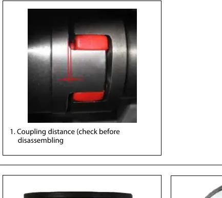
- Coupling: Document the coupling distance prior to disassembly.
- Shaft Seal: Capture images of the dynamic rubber bellow, the static part surface, and the dynamic part.
- Piston Shoe: Provide views of the sliding face (including close-ups), the back side, and the joint bearing.
- Piston Rod: Document the surface condition.
- Swash Plate: Photograph the surface and the internal bearing area.
- Retainer Ball and Plate: Document the retainer guide ball, the upper side of the plate, and internal/centre bearings.
- Port Plate: Capture the upper side, close-up details, and the bearing surface.
- Valve Plate: Document the surface and the thrust pad area.
- Housing and Cylinder Barrel: Provide images of the housing, the outer surface of the cylinder barrel, internal bushings, the shaft surface, and the pins/springs assembly.
Related manuals
Related manuals from the same brand or category.
Electronics / Monitors
Danfoss EKA 163A / 164A Display Instructions
DanfossGeneral / Other Manuals
Danfoss 160SZ Refrigeration Lubricant Safety Information
DanfossGeneral / Other Manuals
Danfoss 160P Refrigeration Oil Safety Data
DanfossFurniture / Home Furnishing
Danfoss Series 51 160cc Variable Displacement Motors Parts Manual
DanfossGeneral / Other Manuals
Danfoss RA 15/6T and RA 15/6TB Conversion Valve Instructions
DanfossGeneral / Other Manuals
Danfoss Intelligent Purging System (IPS 8) Ammonia User Guide
DanfossHome Appliances / Refrigerators
Danfoss DEVIreg Plug-In Electronic Thermostat
DanfossGeneral / Other Manuals
Danfoss VLT HVAC Basic Drive Decoupling Plate Mounting Instructions (H7 and H8)
DanfossGeneral / Other Manuals
Danfoss VLT HVAC Basic Drive IP21 Kit Installation Guide
Danfoss
Manual page author
Michael Turner
Technical manual editor
Reviews PDF manuals for structure, safety notes, and practical product details so readers can find the right information quickly.