HVAC / Thermostats & Controls
Danfoss Ally Boiler Relay 014G2479 Installation and User Guide
Quick installation and setup guide for the Danfoss Ally Boiler Relay (014G2479). Includes wiring diagrams, terminal connections, and technical specifications.
Table of contents
Quick guide from the manual
The Danfoss Ally Boiler Relay (014G2479) is a smart home device designed to control boiler heating systems. This document provides essential installation and wiring instructions. Please note that installation must be performed by trained professionals in accordance with local building regulations.
Installation
To install the device:
- Ensure the power is disconnected.
- Remove the front cover of the unit.
- Mount the back plate of the Danfoss Ally Boiler Relay directly to the wall or onto a wall box.
Wiring and Connections
Proper wiring is critical for safe operation. Always refer to your specific boiler's manual to identify the correct terminals before connecting the relay.
- N: Mains power 230VAC (neutral).
- L: Mains power 230VAC (phase).
- 1: No connection (leave blank).
- 2 (COM): Common of relay change-over switch.
- 3 (ON): Connects to COM when heat is on (NO).
- 4 (OFF): Connects to COM when no heat is requested (NC).
- E: Extra terminal for fixing unused wires (no connection).
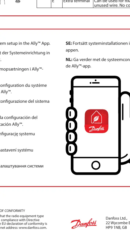
System Setup
After physical installation and wiring, continue the system configuration using the Ally App on your smartphone. Ensure you have downloaded the app as instructed by your gateway manual.
Technical Specifications
- Power supply: Mains 230V~ 50/60 Hz
- Output: Volt free 3(1)A at 250V~
- Operating temperature: 0 °C to 40 °C
- Terminals: Max 2.5 mm² wires
- Controller type: 1B
- Software class: A
- Over voltage category: III
Safety and Disposal
The device is not a toy and must be kept away from children. Do not attempt to dismantle the unit, as it contains no user-serviceable parts. Dispose of the device as e-waste according to local regulations.
Manufacturer information
Danfoss A/S
Practical help
Common problems
Installation difficulties
Installation must be performed by trained professionals. Ensure compliance with local building regulations.
Identifying boiler terminals
Always consult the specific instruction manual provided by your boiler manufacturer to identify the correct terminals.
Before use
- Ensure power is disconnected before starting installation.
- Verify local building regulations for placement.
- Download the Ally App on your smartphone.
- Consult the boiler's manual for terminal identification.
- Ensure wires are within the 2.5 mm² limit.
Specs in practice
- Power supply
- Requires mains 230V~ 50/60 Hz input.
- Operating temperature
- Device functions within 0 °C to 40 °C.
Images and diagrams
- Terminal N: Neutral mains power connection.
- Terminal L: Phase mains power connection.
- Terminal 2 (COM): Common connection for the relay switch.
- Terminal 3 (ON): Normally Open (NO) contact, closes when heat is requested.
- Terminal 4 (OFF): Normally Closed (NC) contact, opens when heat is requested.
Model compatibility
- Not intended for children; do not use as a toy.
- Contains no user-serviceable parts; do not dismantle.
- Must be disposed of as electronic waste.

Manual page author
Emily Carter
User documentation editor
Prepares concise manual descriptions and highlights the most useful setup, operation, and maintenance information for readers.