HVAC / Thermostats & Controls
Installation and Pre-setting Guide for Danfoss 013G7390 Integrated Valve
Learn how to install the Danfoss 013G7390 integrated valve and adjust its pre-setting for optimal radiator flow. Includes torque specifications, tool requirements, and alignment tips.
Table of contents
Manual images
Click an image to enlargeQuick Guide from the Manual
This document provides instructions for the installation and pre-setting of the Danfoss 013G7390 integrated valve. The primary installation requirement is to tighten the valve to a torque of 30–35 Nm using a 21mm ring spanner. Pre-setting is performed using the red scale ring before the sensor is fitted.
Installation
Follow these steps to install the valve into the radiator:
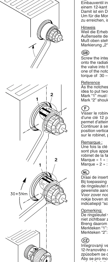
- Screw the integrated valve into the radiator until it is hand-tight and the flange is flush against the radiator connection.
- Use a 21mm ring spanner to tighten the valve further.
- Rotate the valve by an angle of 30° (equivalent to one notch on the valve body). This ensures the required torque of 30–35 Nm.
- Ensure the valve is aligned correctly so that the sensor can be mounted properly.
Tip for installation: Since the notches on the valve body are obscured by the spanner, it is recommended to mark the outside of the ring spanner for guidance:
- Mark "1": Must be at the top position.
- Mark "2": Represents the minimum tightening angle (distance between two notches).
Pre-setting
The flow values can be adjusted precisely without tools before the sensor is installed:
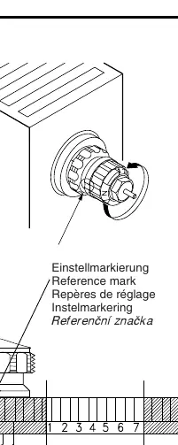
- Locate the red scale ring on the valve.
- Rotate the ring to align the desired pre-setting figure with the reference mark on the valve body.
- Setting "N" indicates that the valve is fully open.
For detailed capacity charts and specific flow rates, refer to the technical data provided by the radiator manufacturer or Danfoss documentation.
Manufacturer information
Danfoss A/S
Practical help
Common problems
Notches on the valve body are not visible while using the spanner.
Mark the outside of your 21mm ring spanner with two marks: '1' for the top position and '2' for the minimum tightening angle (30°).
Valve alignment is incorrect after tightening.
Ensure the valve is tightened to the next notch (30°) so the alignment mark is at the top, allowing for proper sensor mounting.
Before use
- 21mm ring spanner
- Radiator connection must be clean and ready
- Ensure valve is hand-tight before applying the spanner
- Verify the desired pre-setting value before mounting the sensor
Images and diagrams
- The installation diagram illustrates the use of a 21mm ring spanner to tighten the valve to the correct torque.
- The pre-setting diagram shows the red scale ring and how to align the setting with the reference mark.
Model compatibility
- Designed for RA-N series radiator systems.

Manual page author
Michael Turner
Technical manual editor
Reviews PDF manuals for structure, safety notes, and practical product details so readers can find the right information quickly.