Hvac / Thermostats Controls
Installation Guide for Danfoss 077Z7 Service Thermostats
Quick installation guide for Danfoss 077Z7 series service thermostats. Includes wiring diagrams, capillary specifications, and temperature setting charts for models 077Z7010 through 077Z7017.
Table of contents
Quick Guide from the Manual
This document provides installation and technical specifications for the Danfoss 077Z7 series service thermostats, covering models 077Z7010 through 077Z7017. Users should refer to the specific model diagram for wiring and capillary length requirements. Note that all temperatures are measured at 760 mm Hg.
Wiring and Connections
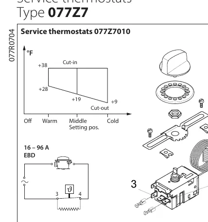
The thermostats utilize specific terminal configurations. Most models use terminals 3 and 4. Model 077Z7017 utilizes terminals 3, 4, and 6. Ensure all electrical connections adhere to local codes and safety guidelines.
Capillary and Sensor Installation
Each model has a specific capillary length (L). When mounting the sensor on the evaporator, ensure the minimum sensor length (LS) is respected. For air sensor applications, the minimum length is 2 x LS. Refer to the specific model data for the exact L and LS values.
Temperature Settings
The thermostats feature adjustable settings (Off, Warm, Middle, Cold). Each model has a specific cut-in and cut-out temperature range in °F. Refer to the chart corresponding to your specific model to understand the temperature behavior at different dial positions.
Safety and Refrigerants
The 077Z7...EBD and 077Z7...L EBD models are compatible with systems using R290 and R600a refrigerants. Always follow local safety guidelines. In countries without specific conformity certifications (UL, CE, CCC, CSA, EAC, etc.), third-party approval is recommended for systems containing flammable refrigerants.
Manufacturer information
Danfoss A/S
Practical help
Common problems
System not cooling or cycling incorrectly
Verify the thermostat dial setting (Off, Warm, Middle, Cold) against the specific cut-in/cut-out chart for your model.
Sensor mounting issues
Ensure the sensor length mounted on the evaporator meets the minimum LS requirement specified for your model.
Before use
- Identify your specific model number (e.g., 077Z7010).
- Check the required capillary length (L) for your installation.
- Verify the wiring configuration (terminals 3, 4, or 6).
- Confirm compatibility with your refrigerant type (R290/R600a for EBD/L EBD models).
- Ensure local safety codes are met for flammable refrigerants.
Specs in practice
- L (Length of capillary)
- The total length of the capillary tube in inches.
- LS (Min. sensor length)
- The minimum length of the sensor that must be in contact with the evaporator.
- Cut-in/Cut-out
- The temperature points at which the thermostat switches the system on (cut-in) or off (cut-out).
Images and diagrams
- The diagrams show the electrical terminal layout (3, 4, 6) and the physical connection points for the capillary tube.
- Temperature charts illustrate the relationship between the dial position and the cut-in/cut-out temperatures in °F.
Model compatibility
- Compatible with R290 and R600a refrigerants for 077Z7...EBD and 077Z7...L EBD models.
- Third-party approval recommended for flammable refrigerant systems in countries without specific conformity certifications.

Manual page author
Michael Turner
Technical manual editor
Reviews PDF manuals for structure, safety notes, and practical product details so readers can find the right information quickly.