General / Accessories
Danfoss ECL Comfort 100M Mounting and Installation Guide
Comprehensive installation and mounting instructions for the Danfoss ECL Comfort 100M weather-compensated controller, including wiring diagrams and physical mounting steps.
Table of contents
Manual images
Jump to the sectionProduct Overview
The Danfoss ECL Comfort 100M is a weather-compensated controller designed for efficient heating system management. This guide provides essential instructions for the physical installation and electrical connection of the unit to ensure optimal performance and safety. Proper mounting is critical for the longevity and accurate operation of the device.
Mounting Instructions
The ECL Comfort 100M is designed for flexible installation options, allowing it to be mounted directly on a wall or onto a standard DIN rail. When wall-mounting, ensure the base is securely fastened to a flat, stable surface. For DIN rail mounting, the unit snaps easily into place, providing a secure fit. Always ensure that the environment is free from excessive moisture or extreme temperatures that could affect the internal electronics.
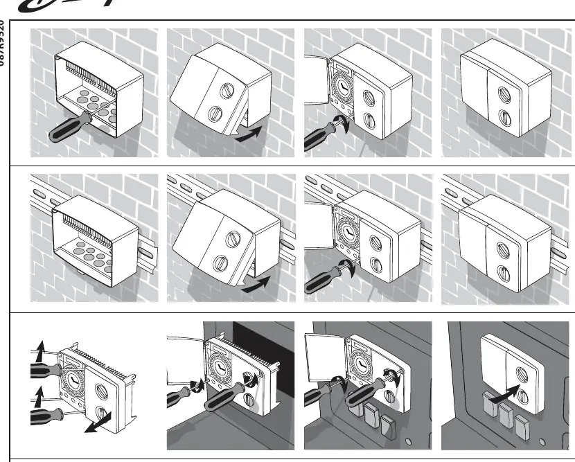
To install the unit, align the controller with the mounting base or rail. Carefully press the unit until it clicks into position. If using a wall-mounted base, ensure the wiring is routed correctly through the designated cable entries before final assembly. The front cover can be removed using a screwdriver to access the terminal blocks for wiring connections. Always ensure the power supply is disconnected before performing any electrical work.
Electrical Connections
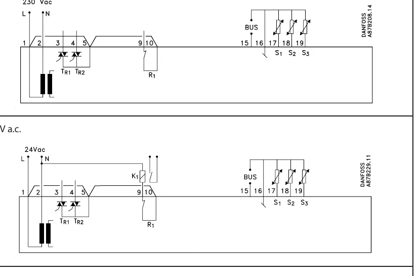
The controller supports both 230V a.c. and 24V a.c. power configurations. It is vital to verify the voltage requirements of your specific model before making any connections. The terminal blocks are clearly marked to facilitate accurate wiring. The system supports various sensors (S1, S2, S3) and bus communication, which are essential for weather-compensated operation. Ensure that all connections are tight and that no loose wires are exposed, as this could lead to short circuits or system failure.
Safety and Maintenance
Safety is paramount during the installation process. Always adhere to local electrical codes and regulations. The device should only be installed by qualified personnel. Maintenance involves periodic checks of the electrical connections to ensure they remain secure and free from corrosion. Keep the unit clean and free from dust accumulation, which can interfere with the internal components. If the unit fails to operate, check the power supply and verify that all sensor connections are correctly seated according to the provided wiring diagrams. Do not attempt to open the internal circuitry of the controller, as this will void the warranty and may pose a safety risk.
Manufacturer information
Danfoss A/S
Practical help
Common problems
Controller fails to power on
Verify that the power supply matches the unit specifications (230V or 24V) and check that all terminal connections are secure.
Inaccurate temperature regulation
Check the sensor connections (S1, S2, S3) to ensure they are correctly wired and that the sensors are not damaged.
Before use
- Verify the supply voltage (230V or 24V).
- Ensure the mounting surface is stable and level.
- Check that all necessary sensors are available.
- Disconnect power before starting installation.
- Verify that cable entries are clear of debris.
- Confirm that the DIN rail or wall mount is secure.
Images and diagrams
- The diagrams illustrate the terminal layout for both 230V and 24V power inputs.
- Terminals 1 and 2 are designated for the main power supply.
- Terminals 15-19 are used for sensor and bus communication connections.
- The physical mounting diagrams show the step-by-step process for wall and DIN rail attachment.
Model compatibility
- Ensure the controller model matches the voltage of your heating system.
- Only use compatible Danfoss sensors for the S1-S3 inputs.

Manual page author
Michael Turner
Technical manual editor
Reviews PDF manuals for structure, safety notes, and practical product details so readers can find the right information quickly.