Industrial / Electrical
Installation Guide for Danfoss 027F3374 Overhaul Kit
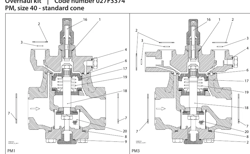
Quick guide for the Danfoss 027F3374 Overhaul Kit. Includes exploded view diagrams for PM1 and PM3 valves, detailed parts list with dimensions, and assembly notes for size 40 standard cone valves.
Table of contents
Quick guide from the manual
This document provides the installation and parts breakdown for the Danfoss 027F3374 Overhaul Kit, designed specifically for PM size 40 valves with a standard cone. Users should refer to the exploded diagrams to identify the correct placement of components for PM1 and PM3 valve configurations.
Product overview
The overhaul kit is intended for maintenance of PM size 40 valves. The manual provides two distinct exploded view diagrams to assist in the assembly process for both PM1 and PM3 valve types. Ensure you identify the correct valve type before beginning the overhaul.
Parts list and specifications
The kit contains 20 specific parts. Each part is identified by a number corresponding to the exploded diagrams. When performing maintenance, verify the material type (Alu or Fibre) and the dimensions provided for each component:
- Parts 1-9: Various seals, gaskets, and rings with specific diameters ranging from 9mm to 93mm.
- Parts 16-20: Internal valve components including springs and filters.
- Note on Part 10: Part 10 is included in the package but is not used for PM 1 or PM 3 valves with a standard cone.
Manufacturer information
Danfoss A/S
Practical help
Common problems
Part 10 is included in the kit but not used
Do not attempt to install part 10 if you are servicing a PM 1 or PM 3 valve with a standard cone.
Before use
- Verify the valve model is PM size 40.
- Ensure the valve configuration is standard cone.
- Identify the valve type (PM1 or PM3) to match the correct exploded diagram.
- Check all parts against the provided dimensions and material types (Alu/Fibre) before assembly.
Images and diagrams
- The diagrams show the exploded view of the PM1 and PM3 valves, identifying the location of parts 1 through 20.
Model compatibility
- Designed specifically for PM size 40 valves with a standard cone.

Manual page author
David Miller
Documentation analyst
Organizes user manual content into clear summaries, with attention to model details, product context, and everyday usability.