Industrial / Electrical
Danfoss 027F3371 Overhaul Kit Installation Guide
Installation guide for the Danfoss 027F3371 overhaul kit, designed for PM size 25 valves. Includes exploded view diagrams for PM1 and PM3 models, a comprehensive parts list, and material specifications.
Table of contents
Manual images
Click an image to enlargeImportant Information
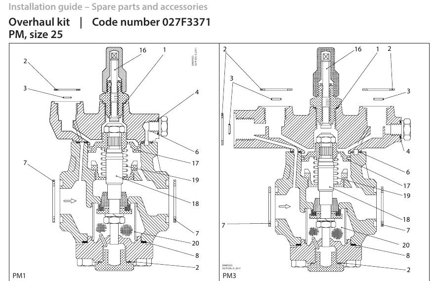
This document provides the necessary exploded view diagrams and parts identification for the Danfoss 027F3371 overhaul kit, specifically designed for PM size 25 valves. Before beginning maintenance, identify whether your valve is a PM1 or PM3 model, as assembly requirements differ.
Product Overview
The guide features detailed exploded view diagrams for both PM1 and PM3 valve configurations. These diagrams illustrate the correct placement of components 1 through 20. Ensure you reference the correct diagram for your specific valve model to avoid incorrect assembly.
Parts List and Specifications
The kit contains various components made of either Aluminum (Alu.) or Fibre. Each part is numbered and corresponds to the exploded view diagrams. Please note the following:
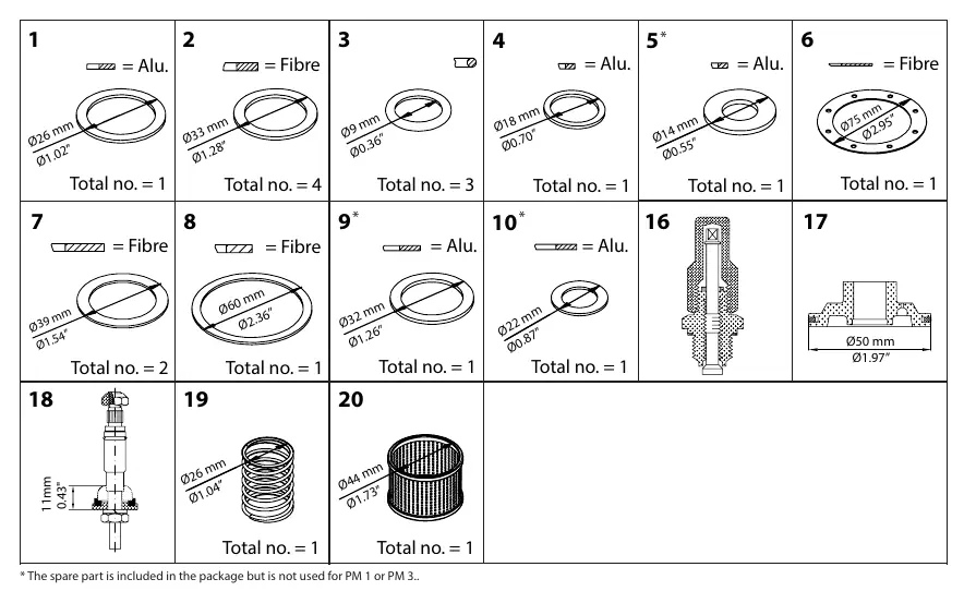
- Material Types: Components are specified as either Aluminum or Fibre. Ensure the correct material is used for the corresponding seal or gasket location.
- Unused Parts: Some spare parts included in the package are not used for PM1 or PM3 configurations. Do not be alarmed if you have leftover parts after completing the assembly for these specific models.
- Dimensions: The guide provides specific dimensions (e.g., diameter in mm and inches) for each part to assist in identification.
Maintenance and Assembly
When performing an overhaul, follow the exploded view diagram carefully. Ensure the valve is fully depressurized and isolated from the system before attempting any disassembly or part replacement. Verify that all seals and components are seated correctly according to the diagram before re-pressurizing the system.
Manufacturer information
Danfoss A/S
Practical help
Common problems
Leftover parts after assembly
Some spare parts included in the kit are not required for PM1 or PM3 configurations. Verify your specific valve model against the provided diagrams to confirm which parts are necessary.
Difficulty identifying parts
Refer to the exploded view diagrams for PM1 and PM3. Each part is numbered (1-20) and cross-referenced with the parts table, which includes material type and dimensions.
Before use
- Identify your valve model (PM1 or PM3).
- Ensure the valve is depressurized and isolated from the system.
- Verify all parts against the exploded view diagram.
- Check material types (Alu. vs Fibre) for each component.
- Clean the valve body surfaces before installing new seals.
Images and diagrams
- The top section of the document provides exploded view diagrams for PM1 and PM3 valves, showing the internal assembly sequence.
- The bottom section provides a detailed table of parts 1-20, including material specifications and dimensions.

Manual page author
Michael Turner
Technical manual editor
Reviews PDF manuals for structure, safety notes, and practical product details so readers can find the right information quickly.