HVAC / Heat Pumps
Installation Instructions for Danfoss Additional Fan
Comprehensive installation guide for Danfoss additional fans. Includes mounting procedures for various compressor models (HG and F series) and electrical connection diagrams.
Table of contents
Manual images
Click an image to enlargeQuick Guide
This manual provides installation instructions for Danfoss additional fans designed for various compressor models. Before starting, ensure you have the correct kit for your specific compressor model. The installation involves mounting a bracket to the cylinder cover and fastening the fan to the bracket. Crucial: Always compare the nameplate data of the fan with the existing voltage and frequency of your power supply before starting the motor.
Installation Overview
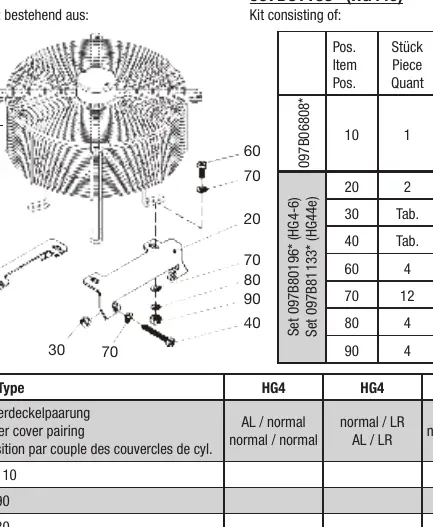
The installation process is similar across different models but requires specific hardware (screws, spacers, washers) as detailed in the tables for each model. The general procedure is as follows:
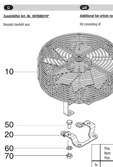
- Identify the correct installation page for your compressor model (e.g., HG12P, HG22P/e, HG4, HG7, etc.).
- Remove the corresponding screws from the cylinder cover at the designated attachment points.
- Mount the provided bracket (Pos. 20) using the screws specified in the model-specific table.
- Fasten the fan (Pos. 10) to the bracket using the provided attachment parts (screws, washers, lock washers, nuts, and spacers where applicable).
- Ensure all components are tightened securely according to the diagram provided for your specific model.
Electrical Connection
The electrical connection must be performed according to the provided wiring diagram. Ensure the power supply matches the motor specifications.
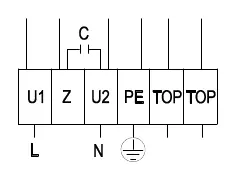
- L: Phase (Blue)
- Z: (Brown)
- N: Neutral (Black)
- PE: Protective Earth (Green/Yellow)
- TOP: Thermal Overload Protector (Gray)
The motor may only be started up when the voltage and frequency comply with the nameplate data.
Safety and Compatibility
Note that legacy BOCK reference numbers do not include the '097B' prefix. Always verify the kit contents against the table provided for your specific model on the corresponding page. If the voltage and frequency do not match, do not start the motor.
Manufacturer information
Danfoss A/S
Practical help
Common problems
Motor does not start or runs incorrectly
Verify that the power supply voltage and frequency match the data on the fan's nameplate.
Incorrect mounting hardware
Ensure you are using the specific screws and spacers listed in the table for your exact compressor model (e.g., M10x20 vs M10x70).
Before use
- Compare nameplate voltage and frequency with your power supply.
- Identify your compressor model and locate the corresponding installation page.
- Verify all kit components (bracket, screws, washers, spacers) are present.
- Ensure the cylinder cover attachment points are clean and accessible.
Images and diagrams
- The wiring diagram illustrates the connection points for L, Z, N, PE, and TOP terminals.
- The installation diagrams show the assembly order of the bracket, fan, and fasteners.
Model compatibility
- Mounting hardware varies significantly by model (HG12P, HG22P/e, HG4, HG7, HG8, F-series). Always refer to the specific page for your model.
- Some models require specific spacers (e.g., Pos. 75 or 80) to ensure correct fitment.

Manual page author
Michael Turner
Technical manual editor
Reviews PDF manuals for structure, safety notes, and practical product details so readers can find the right information quickly.