Plumbing / Valves & Fittings
Danfoss RA 15/6T and RA 15/6TB Conversion Valve Installation Guide
Quick installation guide for Danfoss RA 15/6T and RA 15/6TB conversion valves. Learn how to correctly mount the valve body to the radiator and attach the thermostatic sensor head using the click-on mechanism.
Table of contents
Quick guide from the manual
This document provides essential instructions for the installation of Danfoss RA 15/6T and RA 15/6TB conversion valves. The guide focuses on the physical connection of the valve body to the radiator and the subsequent attachment of the thermostatic sensor head.
Installation procedure
The installation process involves two main steps for both the RA 15/6T and RA 15/6TB models:
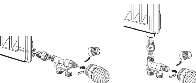
- Valve Body Mounting: Secure the valve body onto the radiator connection. Ensure the thread size matches your specific radiator setup (available in 1/2 inch or 3/4 inch variants depending on the model code).
- Sensor Head Attachment: Once the valve body is securely installed, align the thermostatic sensor head with the valve body. Push the sensor head onto the valve until you hear a distinct click, indicating that it is locked in place.
Compatibility and models
The manual covers the following valve series:
- RA 15/6T: Compatible with various 1/2 inch and 3/4 inch connection codes (e.g., 013G3218, 013G3270, 013G3260, 013G3224, 013G3280, 013G3220).
- RA 15/6TB: Compatible with 1/2 inch connection codes (013G3215, 013G3210).
Manufacturer information
Danfoss A/S
Practical help
Common problems
Sensor head does not stay attached
Ensure the sensor head is pushed firmly onto the valve body until the 'click' mechanism engages fully.
Before use
- Verify the valve model (RA 15/6T or RA 15/6TB) matches your radiator requirements.
- Check the connection size (1/2 inch or 3/4 inch) against your existing pipework.
- Ensure the radiator system is depressurized before attempting installation.
Images and diagrams
- The diagrams illustrate the horizontal and vertical mounting orientations for the valve bodies.
- The arrows indicate the direction of the click-on motion required to attach the thermostatic sensor head.
Model compatibility
- Ensure the specific product code (e.g., 013G3218) matches the required thread size for your installation.

Manual page author
Michael Turner
Technical manual editor
Reviews PDF manuals for structure, safety notes, and practical product details so readers can find the right information quickly.