Electronics / Monitors
Disassembly Guide for DELL U2424HEB Monitor
Step-by-step disassembly instructions for the DELL U2424HEB monitor, including tool requirements and component removal procedures for recycling and maintenance.
Quick answers from the manual
Quick answer
- This document is a service manual detailing the step-by-step disassembly procedures for the DELL U2424HEB monitor, primarily for recycling and component recovery purposes. p. 1
Key actions
- Remove the stand p. 1
- Disassemble the rear cover p. 1
Where to find it in the PDF
- Disassembly Procedures p. 1, 2, 3, 4
- Material Information p. 7
Table of contents
Manual images
Click an image to enlargeImportant Information
This document provides detailed disassembly procedures for the DELL U2424HEB monitor. It is intended for authorized service personnel or recycling facilities to safely remove components in compliance with WEEE directives. Please follow the steps in the specified order to avoid damage to the device.
Tools Required
To disassemble the monitor, you will need the following tools:
- Philips-head Screwdriver
- Penknife
- Bar scraper
Disassembly Procedures
Stand and Rear Cover Removal
- Stand Removal: Place the monitor on a soft cloth or cushion. Press and hold the stand release button, then lift the stand up and away from the monitor.
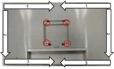
- Rear Cover: Unlock the 4 screws on the rear cover. Use your hands or a scraper bar to disassemble the cover. Note the disassembly order: Top Side, then Right/Left Side, then Bottom Side.
Internal Component Removal
- CTRL BD: Pull out the CTRL BD FFC from the I/F BD and tear it off from the Main SHD. Remove the tape and unlock the 3 screws to disassemble the CTRL BD.
- Sensor BD: Pull out the ALS FFC from the I/F BD and tear off the tape. Disassemble the Sensor BD from the middle frame and unplug the ALS FFC.
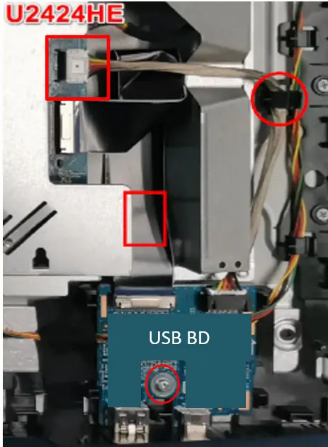
- USB BD: Press and pull the lock of the connector to disassemble the USB BD FFC from the I/F BD. Unlock the screw to disassemble the USB BD from the middle frame.
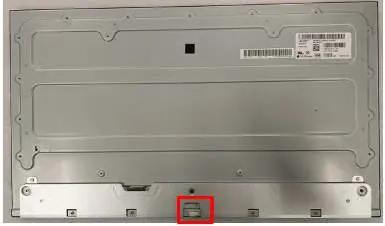
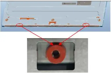
- Middle Frame: Unlock the 11 screws (red marks) and 4 screws on the bottom side (blue marks) to remove the middle frame from the panel.
- Internal Boards: Unlock the 10 PCBA screws to disassemble the I/F BD, SPS BD, and LED Driver BD from the Main SHD.
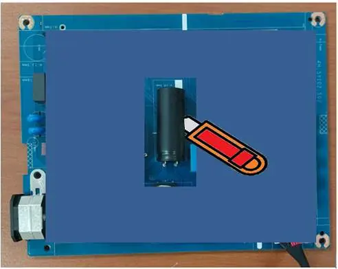
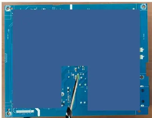
Capacitor Removal
To remove electrolyte capacitors from the printed circuit boards:
- Cut the glue between the bulk capacitor and the PCB with a knife.
- Ensure the cutting path remains within the glue to avoid damaging the capacitor or the PCB.
- Use a soldering iron and absorber to remove the pin solder.
- Lift the capacitor up and away from the PCB.
Product Material Information
The monitor contains components that must be disposed of or recovered separately in compliance with Article 4 of EU Council Directive 75/442/EEC, including printed circuit boards, LCD displays, and electrolyte capacitors.
Manufacturer information
Dell Inc.
Practical help
Common problems
Difficulty removing the rear cover
Ensure you follow the specific disassembly order: Top Side, then Right/Left Side, then Bottom Side.
Risk of damaging USB BD FFC connector
Always press the lock on the connector before pulling it out from the I/F BD.
Before use
- Ensure the monitor is powered off.
- Prepare a soft cloth or cushion to protect the screen.
- Gather required tools: Philips-head screwdriver, penknife, and bar scraper.
- Verify the model is DELL U2424HEB.
Show more Show less
Images and diagrams
- The manual provides visual guides for screw locations and cable disconnection points.
- Specific torque values are provided for reassembly: 8-9Kgf for rear cover screws, 1.6-1.8Kgf for CTRL BD screws, and 4-5Kgf for USB BD and Middle Frame screws.
Model compatibility
- This guide is specific to the DELL U2424HEB model.

Manual page author
Michael Turner
Technical manual editor