Electronics / Monitors
Disassembly Guide for Dell U2724DE Computer Monitor
A comprehensive service and disassembly guide for the Dell U2724DE computer monitor, providing step-by-step instructions for component removal, tool requirements, and material recovery information.
Quick answers from the manual
Quick answer
- This document is a service manual detailing the step-by-step disassembly procedures for the Dell U2724DE computer monitor, intended for recycling and component recovery. p. 1, 2, 3, 4
Key actions
- Remove the stand by pressing the release button. p. 1
- Remove the rear cover by wedging fingers between the cover and bezel. p. 1
- Remove electrolyte capacitors using a soldering iron and absorber. p. 4
Where to find it in the PDF
- Disassembly Steps 1-7 p. 1
- Disassembly Steps 8-13 p. 2
- Disassembly Steps 14-19 p. 3
- Capacitor Removal and Material Info p. 4, 5
Table of contents
Manual images
Click an image to enlargeQuick guide from the manual
This document provides detailed, step-by-step instructions for the disassembly of the Dell U2724DE computer monitor. It is intended for service personnel and recycling facilities to safely remove components and recover materials in compliance with environmental regulations.
Tools Required
To perform the disassembly, the following tools are typically required:
- Screwdriver (Phillips head) #1
- Screwdriver (Phillips head) #2
- Penknife
- Soldering iron and absorber
Disassembly Procedures
The disassembly process involves removing the stand, rear cover, and internal boards. Please follow these steps in order:
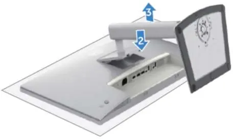
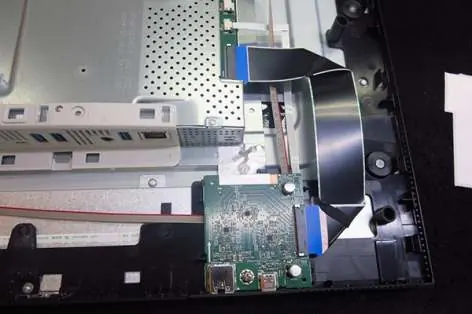
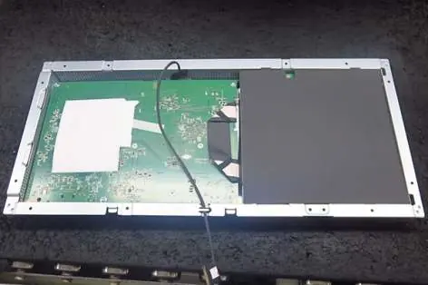
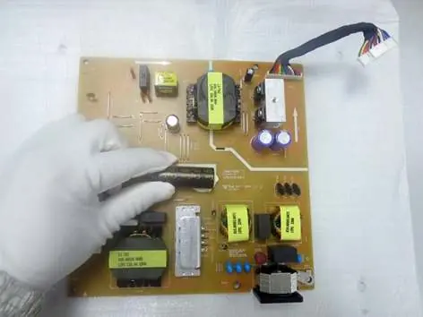
- Stand Removal: Press the stand release button and lift the stand away from the monitor.
- Rear Cover Removal: Wedge fingers between the rear cover and middle bezel to release the cover. Disconnect the joystick key cable and sensor cable before fully removing the cover.
- Internal Components: Use the specified Phillips screwdrivers to remove screws securing the interface board, power board, TBT board, and USB board. Note that different screw sizes (e.g., M4x11, M3x5, M3x6) and torque values are specified for different components.
- Capacitor Removal: Electrolyte capacitors must be removed from the printed circuit boards using a soldering iron and absorber. Use a knife to carefully cut the glue between the bulk capacitor and the PCB before desoldering.
Product Material Information
The monitor contains components that must be disposed of or recovered separately in compliance with EU Council Directive 75/442/EEC. This includes printed circuit boards larger than 10 square cm, LCD displays larger than 100 cm2, and electrolyte capacitors larger than 25mm in height and diameter.
Manufacturer information
Dell Inc.
Practical help
Common problems
Difficulty removing the rear cover
Ensure you are wedging fingers between the rear cover and middle bezel at the top corners, then use one hand to press the middle bezel while pulling the rear cover carefully.
Removing bulk capacitors
Cut the glue between the capacitor and PCB with a knife first, ensuring the cutting path does not touch the capacitor or PCB, then use a soldering iron and absorber to remove the pin solder.
Before use
- Ensure you have a Phillips head screwdriver #1 and #2.
- Have a penknife ready for glue removal.
- Prepare a soldering iron and absorber for capacitor removal.
- Work on a clean, protective surface to avoid damaging the panel.
Show more Show less
Specs in practice
- Torque values
- Specific torque settings (e.g., 11±1kgfxcm) are provided for screws to ensure components are secured correctly without damaging the plastic or threads.
Images and diagrams
- The manual provides visual steps (S1-S20) showing exactly where to apply pressure, where to disconnect cables, and which screws to remove.
- Red markings in diagrams indicate specific components to be removed or screws to be unscrewed.
Model compatibility
- This guide is specific to the Dell U2724DE model.

Manual page author
Emily Carter
User documentation editor