Power / Batteries Chargers
Diodes 10W AP3928 EV1 Evaluation Board User Guide
Technical user guide for the AP3928 EV1 evaluation board, a 10W non-isolated buck regulator designed for home appliances and IoT auxiliary power.
Table of contents
Manual images
Jump to the sectionProduct Overview
The AP3928 EV1 is an evaluation board for a 10W, non-isolated buck regulator. It is designed to provide an accurate constant voltage (CV) output, making it suitable for home appliances such as AC fans, rice cookers, air conditioners, coffee machines, and soy milk machines, as well as auxiliary power for IoT devices.
Key Features and Specifications
- Input Voltage: Universal 85V to 265V AC.
- Output: 18V / 550mA (9.9W).
- Efficiency: High efficiency at light loading, meeting DOE and CoC requirements.
- Standby Power: Very low,
- Protection: Includes Over-Temperature Protection (OTP), Over-Load Protection (OLP), Open-Loop Detection (OLD), and Short-Circuit Protection (SCP).
- Compliance: RoHS compliant, lead-free, halogen and antimony-free.
Quick Start Guide
The evaluation board is factory-preset to 18V/550mA output. Follow these steps for operation:
- Ensure the AC source is switched OFF or disconnected before making connections.
- Connect the AC line wires to the L and N connectors located on the left side of the board.
- Turn on the AC main switch.
- Measure the +V and GND connectors to verify the output voltage is 18V.
Safety Warning
CAUTION: This evaluation board is non-isolated. Do not touch any part of the board while it is connected to an AC power source, as all electrical connections are coupled to high voltage potential.
Performance and Testing
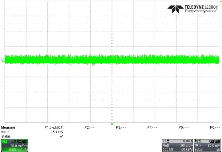
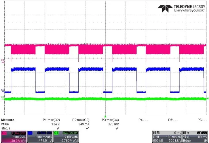
The board has been tested for various performance metrics, including startup time, rise time, voltage stress, output ripple and noise, and dynamic response. It meets EN55022 Class B EMI requirements with a margin of more than 6dB for both 110V and 230V inputs.
Manufacturer information
Diodes Incorporated
Practical help
Common problems
Output voltage instability
Check if the load exceeds the 550mA rated current, which may trigger Overload Protection (OLP).
No output voltage
Verify the input fuse (F1) has not blown due to a short circuit or overcurrent event.
Before use
- Ensure the AC source is disconnected before wiring.
- Verify that the AC input is within the 85V-265V range.
- Check that the load does not exceed 550mA.
- Ensure the board is placed in a safe, non-conductive area due to high voltage exposure.
Specs in practice
- Input Voltage
- Universal 85V to 265V AC range allows global use.
- Output Current
- Maximum rated output current is 600mA; the board is preset for 550mA.
- Standby Power
- Less than 30mW at no load, ensuring high energy efficiency.
Images and diagrams
- Figure 1 & 2: Top and bottom views of the PCB showing component placement.
- Figure 3: Schematic diagram of the evaluation board.
- Figure 4 & 5: PCB layout diagrams for top and bottom layers.
Model compatibility
- The board is non-isolated; it must not be used in applications requiring galvanic isolation.
- Designed for 18V/550mA output applications.

Manual page author
Emily Carter
User documentation editor
Prepares concise manual descriptions and highlights the most useful setup, operation, and maintenance information for readers.