Tools / Soldering Stations
Draper 50, 100 & 120 Litre Air Compressor
Quick guide for Draper 50, 100, and 120 Litre air compressors (Models DA100/15BLA, DA50/90HP, DA100/15HP, DA120/29HP). Includes installation, operation, maintenance, and troubleshooting steps.
Table of contents
Manual images
Click an image to enlargeQuick Guide from the Manual
This manual covers the operation and maintenance of Draper 50, 100, and 120 Litre air compressors. Before using the equipment, ensure the oil level is correct, the drain valve is closed, and the unit is placed in a well-ventilated area with at least 1 metre of clearance. Always disconnect from the power supply before performing any maintenance.
Installation
After unpacking, perform the following steps:
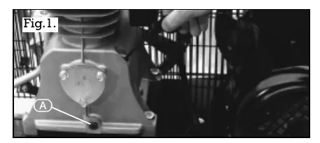
- Replace the plastic shipping cap on the motor housing with the provided oil dipstick.
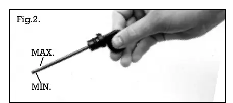
- Check the oil level using the dipstick; ensure it is between the minimum and maximum notches.
- Ensure the compressor is placed in a well-ventilated area with at least 1 metre of safety clearance around the unit.
Operation
The compressor is controlled by a pressure switch assembly that automatically cuts off power when the maximum pressure is reached and restarts when pressure drops below the minimum. To operate:
- Connect the compressor to the power supply.
- Ensure the reservoir drain valve is closed.
- Turn the switch on the pressure switch box to the ON position.
- To stop, turn the switch to the OFF position. Do not switch off at the power supply before turning off the machine.
Maintenance
Regular maintenance is essential for longevity:
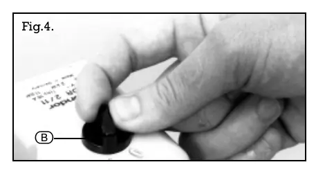
- Every Day: Check oil level and top up if required. Drain condensate from the receiver using the drain plug on the underside of the tank.
- Every Month: Clean the air suction filter using compressed air. Check drive belt tension and adjust if necessary.
- Every 500 Hours: Replace the oil. Clean external surfaces of the pump and motor, ensuring fan cowlings and cooling fins are not obstructed.
- Every 2000 Hours: Check the condition of valves and replace if damaged or worn.
Pressure Switch Adjustments
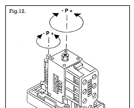
If the delivery pressure drifts, the pressure switch may require adjustment. Remove the switch cover and turn the pressure regulating screw clockwise to increase the cut-out level or anticlockwise to decrease it. Warning: Do not adjust the cut-out level above the maximum pressure specified for the machine.
Troubleshooting
If the compressor fails to start, check the power cable, fuse, circuit breaker, or thermal overload protection. If the unit runs but produces no air, check that all valves are closed and inspect gaskets and drive belts. For further assistance, contact the Power Division Help Line at 01703 494344.
Manufacturer information
Draper Tools
Practical help
Common problems
Compressor will not start
Check power cable, fuse, circuit breaker, or thermal overload protection. Ensure receiver pressure is not higher than the cut-out pressure.
Low air output
Check for kinked hoses, leaking connections, clogged air filter, or loose drive belt.
Noisy operation (knocking)
Check for loose drive pulley, coupling, flywheel, or low oil level.
Thermal overload trips
Check oil level, direction of rotation, or pressure switch failure.
Before use
- Check oil level using the dipstick.
- Ensure the reservoir drain valve is closed.
- Verify adequate ventilation (at least 1 metre clearance).
- Ensure the power switch is in the OFF position before connecting to power.
- Check that the air supply pressure is equal to or less than the air tool's maximum operating pressure.
Specs in practice
- Receiver capacity
- The volume of the air tank (50L, 100L, or 120L).
- FAD (Free Air Delivered)
- The actual volume of air available for tools.
- Maximum pressure
- The highest pressure the compressor will reach before cutting out (145psi/10 bar).
Images and diagrams
- Fig. 1 & 2: Oil dipstick location and level check.
- Fig. 12: Pressure switch adjustment screw locations.
Model compatibility
- Wheels are not supplied as standard.
- Honda petrol engine models require reference to the engine manufacturer's manual.

Manual page author
Emily Carter
User documentation editor
Prepares concise manual descriptions and highlights the most useful setup, operation, and maintenance information for readers.