Tools / Saws
User Manual for Kobalt 17-Gallon Electric Air Compressor
Comprehensive user guide for the Kobalt 17-Gallon Electric Air Compressor (Models 143075 and 236005). Includes assembly instructions, operating procedures, maintenance schedules, troubleshooting, and parts diagrams.
Table of contents
Manual images
Click an image to enlargeQuick guide from the manual
Before using your new air compressor, please note the following critical information:
- Break-in period: Upon first use, open the petcock on the bottom of the tank and let the compressor run for approximately 30 minutes to properly break in all moving parts.
- Daily maintenance: You must drain the moisture from the tank at the end of every workday to prevent internal corrosion.
- Clearance: Ensure the compressor is kept at least 12 inches (31 cm) from any wall or obstruction to provide proper ventilation for cooling.
- Safety: This unit starts automatically. Always shut off the compressor, unplug it, and bleed all pressure from the system before performing any service.
Safety Guidelines
Read and understand all safety precautions before operating. Failure to comply may result in personal injury, property damage, or voiding of the warranty.
- Fire/Explosion: Never spray flammable liquids in a confined area. Operate in a well-ventilated area away from sparks or flames.
- Bursting: Do not weld, drill, or modify the air tank. Do not adjust the pressure switch or relief valve.
- Electrical: Never use the compressor outdoors in the rain or on wet surfaces.
- Personal Protection: Always wear ANSI Z87.1 approved safety goggles and hearing protection. Never point nozzles at people or body parts.
- Burns: Do not touch the pump, manifold, or transfer tube while the unit is running; these parts get very hot.
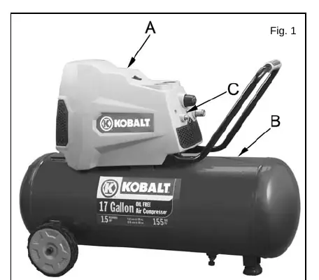
Overview
The basic components of the air compressor are the electric motor, pump, pressure switch, and tank. The motor is factory-lubricated and oil-free. The pressure switch automatically shuts down the motor when the tank reaches the kick-out pressure and restarts it when the pressure drops to the kick-in level.
Assembly
1. Unpack the unit and inspect for damage. The carton should contain the compressor, handle, and manuals.
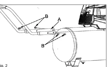
2. Install the handle by placing the handle ends onto the base and securing them with the provided bolts using a 13mm socket or wrench.
3. Position the compressor on a hard, level surface near a grounded electrical outlet. Ensure it is at least 12 inches from any wall.
4. Connect an air hose to the compressor hose outlet.
Compressor Controls
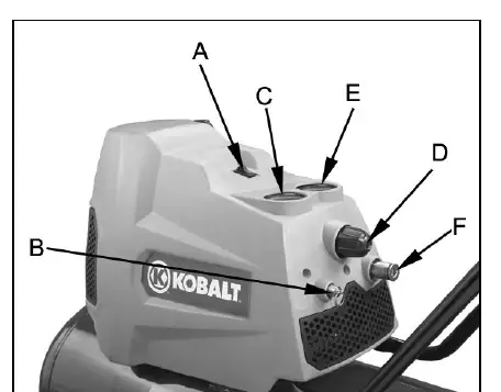
- ON/OFF Switch: Manually turns the unit on or off. When in the ON position, the unit cycles automatically.
- Pressure Relief Valve: Used to manually relieve tank pressure. It also pops open automatically if the pressure switch fails to shut down the motor.
- Tank Pressure Gauge: Displays the air pressure stored in the tank.
- Air Pressure Regulator: Adjusts the line pressure to the tool. Turn clockwise to increase, counterclockwise to decrease.
- Regulated Pressure Gauge: Displays the regulated outlet pressure.
Electrical Power Requirements
This unit is designed for a nominal 115-volt circuit. It must be grounded. Avoid using extension cords; if necessary, use a 3-wire extension cord no longer than 50 feet with a minimum wire size of 12 AWG. Do not use 14 or 16 gauge cords.
Operating Instructions
Daily Startup:
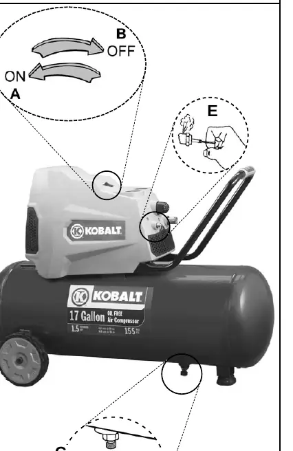
- Ensure the ON/OFF switch is in the OFF position.
- Close the tank petcock by turning it clockwise.
- Plug in the power cord.
- Turn the ON/OFF switch to the ON position.
- Adjust the air pressure regulator to the required working pressure of your tool.
Shutdown:
- Turn the ON/OFF switch to the OFF position.
- Unplug the power cord.
- Reduce tank pressure through the outlet hose or by pulling the relief valve ring.
Maintenance
- Drain Tank: Drain moisture daily via the petcock on the bottom of the tank.
- Relief Valve: Pull the ring daily to ensure it functions properly and is free of obstructions.
- Leaks: Check connections regularly. If a leak is suspected, spray soapy water on the connection; if bubbles appear, tighten or reseal.
- Storage: Clean dust and debris, disconnect power, coil the cord, drain the tank, and cover the unit.
Troubleshooting
If the compressor fails to start, check for a tripped circuit breaker or blown fuse, ensure the motor has cooled if the overload protector tripped, and verify the extension cord size. If the unit does not stop or has low pressure, check for tank leaks, an open petcock, or restricted air intake.
Parts and Service
For replacement parts or service, contact the nearest authorized Service Center or call 1-866-307-4104. Have your model and serial number ready when calling.
Manufacturer information
Kobalt
Practical help
Common problems
Compressor does not stop or low pressure
Check if the tank petcock is open, check for leaks in fittings, or ensure the air intake is not restricted.
Motor will not run
Check for tripped circuit breaker/fuse, ensure motor has cooled (overload protection), or check for loose electrical connections.
Air leaks from regulator
Replace the regulator or internal parts.
Before use
- Inspect unit for shipping damage.
- Ensure the compressor is on a hard, level surface.
- Verify the compressor is at least 12 inches from walls.
- Ensure the tank petcock is closed.
- Check that the power source matches the unit's voltage/amperage requirements.
- Perform the 30-minute break-in procedure.
Specs in practice
- 125 PSI (Kick-in)
- The pressure at which the motor automatically restarts.
- 155 PSI (Kick-out)
- The pressure at which the motor automatically shuts off.
Images and diagrams
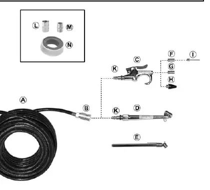
- The parts drawing illustrates the assembly of the motor, pump, tank, and manifold components.
- The accessory connection guide shows how to attach the hose, blowgun, and tire chuck.
Model compatibility
- Use only galvanized steel pipe and fittings for compressed air distribution lines.
- Do not use plastic or PVC pipe for compressed air.

Manual page author
Michael Turner
Technical manual editor
Reviews PDF manuals for structure, safety notes, and practical product details so readers can find the right information quickly.