HVAC / Water Heaters
User Manual for Drija 17L Gas Water Heater
Quick guide for the Drija 17L Gas Water Heater (Model CLT17L). Includes installation requirements, operation instructions, safety precautions, maintenance tips, and troubleshooting for error codes.
Quick answers from the manual
Quick answer
- The Drija 17L Gas Water Heater (CLT17L) is a forced-type gas water heater. It requires professional installation in a well-ventilated area. Operation involves connecting gas and water, plugging into a grounded outlet, and using the control panel to set the desired temperature. p. 2, 8, 9
Key actions
- Installation p. 8
- Operation p. 9
- Maintenance p. 10
First start
- Ensure gas and water valves are open, plug in the unit, and open the hot water tap to trigger automatic ignition. p. 9
Problems and fixes
E0: Probe malfunction
Check connections of water flow transducer and temperature sensor or replace them.
p. 11
E1: Ignition failed
Check if gas valve is open, check gas pressure, or check water pressure.
p. 11, 12
E3: Overheat protection
Restart the water heater.
p. 12Error codes
| Code | Meaning | Action | Pages |
|---|---|---|---|
| E0 | Probe malfunction | Check connections or replace sensor | p. 11 |
| E1 | Ignition failed | Check gas/water supply | p. 11, 12 |
| E3 | Overheat protection | Restart the heater | p. 12 |
Maintenance and reset
- Regularly clean the water inlet filter with a toothbrush. p. 10
Technical specifications
| Parameter | Value | Meaning | Pages |
|---|---|---|---|
| Model | CLT17L | Product model number | p. 5 |
| Heating Power | 34kW | Rated heating power | p. 5 |
| Capacity | 17L/min | Rated capacity of hot water | p. 5 |
Where to find it in the PDF
- Specifications p. 5
- Installation p. 8
- Troubleshooting p. 11, 12
Table of contents
Manual images
Click an image to enlargeQuick guide from the manual
The Drija 17L Gas Water Heater (Model CLT17L) is a forced-type gas water heater designed for residential hot water supply. Important: Installation must be performed by a registered gas installer. The unit requires a well-ventilated area, a reliable grounding device for the electrical connection, and proper flue pipe installation to exhaust waste gas outdoors. Always ensure the gas type matches the rating label (LPG: 2800Pa).
Safety Precautions
- Do not install in bedrooms, basements, living rooms, or bathrooms without proper ventilation and flue pipe exhaust.
- If a gas leak is detected, close the main gas valve, open windows and doors, and do not operate electrical switches.
- Keep flammable materials at least 250mm away from the heater.
- Always check hot water temperature by hand before showering to avoid scalding.
- Do not touch the flue duct during or immediately after operation.
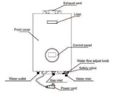
Main Components
The unit features a control panel for temperature settings, a water flow adjustment knob, and clearly marked inlets/outlets for water and gas. The exhaust vent is located at the top of the unit.
Installation
Installation must be done by a registered gas installer. Key requirements include:
- Location: Well-ventilated room with a floor drain. Avoid installation in bedrooms, basements, or living rooms unless specific distance requirements are met.
- Mounting: Fix the heater vertically to the wall with screws, maintaining at least 10mm distance from the wall.
- Piping: Ensure the flue pipe is installed to discharge exhaust outdoors. The gap between the pipe and the wall should be sealed with a 1° leaning angle to prevent water backflow.
- Connections: Confirm gas inlet, water inlet, and water outlet connections are secure and leak-free.
Operation Instructions
- Ensure the gas supply is on and the gas regulator is qualified.
- Open the main gas valve and the water inlet/outlet valves.
- Plug the unit into a grounded electrical outlet.
- Open the hot water tap; the heater will ignite automatically.
- Use the control panel to set the desired temperature (35°C to 65°C).
- Adjust the water flow volume using the knob at the bottom if necessary.
- Close the hot water tap to turn off the flame.
Maintenance
Regular maintenance ensures safe operation:
- Before maintenance, close the gas and water valves and unplug the power.
- Wipe the exterior with a soft towel and kitchen cleanser (do not use benzene or thinner).
- Regularly remove and clean the filter at the water inlet using a toothbrush.
- Check for any abnormal sounds or changes in appearance during operation.
Troubleshooting
If the heater does not operate correctly, check the gas and water supply valves first. If the indicator light is off, check the power connection. If the water is not warm enough, adjust the water flow or temperature settings. The unit features an LED display that shows error codes for specific malfunctions (e.g., E0 for probe malfunction, E1 for ignition failure, E3 for overheat protection).
Practical help
Common problems
Indicator light is not on
Check if the power is off and ensure the plug is firmly connected.
No hot water flow
Check if the gas valve and water valve are fully opened; check for water supply failure.
Water is not warm enough
Check if the gas valve is fully open, ensure hot and cold water are mixed properly, or adjust the water flow volume.
Hot water becomes cloudy
This is normal; it is caused by air bubbles in the water.
Before use
- Ensure the gas type matches the rating label (LPG).
- Verify the gas supply system has no leaks.
- Ensure a qualified gas regulator is used.
- Confirm the flue pipe is installed for outdoor exhaust.
- Check that the electric outlet has a reliable grounding device.
- Ensure the water inlet pressure is sufficient.
Specs in practice
- Rated heating power
- 34kW
- Rated Capacity
- 17L/min (at ΔT=20K)
- Working water pressure
- 0.015~0.8MPa
- Gas pressure
- LPG: 2800Pa
Images and diagrams
- The main components diagram identifies the exhaust vent, control panel, water flow adjust knob, and inlet/outlet connections.
- The installation diagram shows the required clearances and pipe positioning.
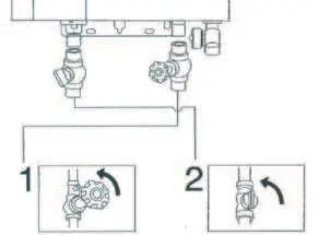
- The operation diagram illustrates the correct valve positions for water and gas.
Model compatibility
- Requires LPG gas supply.
- Requires 110V/50-60Hz power supply.
- Installation must be performed by a registered gas installer.

Manual page author
David Miller
Documentation analyst
Organizes user manual content into clear summaries, with attention to model details, product context, and everyday usability.