HVAC / Water Heaters
User Manual for Bosch C 950 / C 1050 ES Water Heater
Comprehensive installation and operation guide for the Bosch C 950 / C 1050 ES tankless water heater. Includes setup, venting, maintenance, and troubleshooting.
Quick answers from the manual
Quick answer
- The Bosch C 950 / C 1050 ES is a tankless water heater. Installation must be performed by a qualified installer. Key operations include setting temperature via the front panel and regular maintenance like descaling. p. 1, 53, 56
Key actions
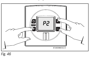
- Adjusting fan speed p. 36
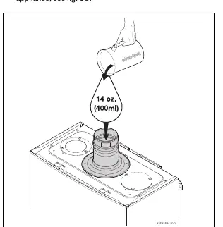
- Filling condensate trap p. 45
First start
- Fill condensate trap p. 45
Problems and fixes
A2 Error
Fault in flue gas limiter. Check continuity and connections.
p. 66Error codes
| Code | Meaning | Action | Pages |
|---|---|---|---|
| A2 | Flue gas limiter fault | Check continuity and connections | p. 66 |
| EA | No flame ionization detected | Verify gas valves, purge air from gas line | p. 68 |
Maintenance and reset
- Reset error code p. 55, 66
Technical specifications
| Parameter | Value | Meaning | Pages |
|---|---|---|---|
| Max flow rate (25°F rise) | 13.1 GPM (C 950) / 14.9 GPM (C 1050) | Maximum output capacity | p. 10 |
Where to find it in the PDF
- Installation p. 15, 40
- Operation p. 52, 55
- Troubleshooting p. 63, 69
Table of contents
Manual images
Click an image to enlargeQuick guide from the manual
This manual provides essential instructions for the installation, operation, and maintenance of the Bosch C 950 / C 1050 ES tankless water heater. Important: Installation must be performed by a qualified installer. Improper installation can lead to property damage, injury, or death. Always ensure proper venting and gas supply pressure before operation.
Appliance details
The Bosch C 950 / C 1050 ES is a high-efficiency, tankless water heater featuring a modulating gas valve and electronic ignition. It is designed for indoor installation and requires specific venting configurations to ensure safe operation.
Installation and setup
Proper installation is critical for safety and performance:
- Venting: The unit must be vented to the outside. Approved materials include PP, PVC, CPVC, and ABS. Follow the specific venting tables provided in the manual based on pipe diameter and length.
- Gas piping: Ensure the gas supply is sized correctly for the maximum BTU input of the unit. A manual gas shutoff valve must be installed.
- Water connections: Use 3/4 inch piping for inlet and outlet. A pressure relief valve must be installed.
- Electrical: The unit requires a 120VAC/60Hz grounded outlet.
- Condensate trap: Must be filled with approximately 14 oz. (400ml) of water before initial startup.
Operation
The unit is controlled via the front panel LCD display:
- Power: Press the On/Off button to start or shut down the appliance.
- Temperature: Use the '+' and '-' buttons to set the desired hot water temperature.
- Reset: If an error occurs, press the reset button to attempt to clear the fault.
Maintenance
Regular maintenance is required to ensure longevity:
- Annual maintenance: Inspect the venting system, combustion chamber, burner, pressure relief valve, and water filter annually.
- Descaling: In areas with high mineral content, the heat exchanger should be flushed with a descaling solution periodically.
- Condensate trap: Check for debris and clean as needed.
Troubleshooting
If the unit displays an error code, consult the troubleshooting section. Common issues include burner ignition failure, water temperature fluctuations, or low water flow. Always verify gas pressure and water flow before calling for service.
Manufacturer information
Bosch
Practical help
Common problems
Burner does not ignite
Check power, gas supply, water flow (min 0.5 GPM), and inlet filter.
Water too hot
Lower temperature setting, clean inlet filter, check for plumbing crossover.
Water not hot enough
Raise temperature setting, check gas pressure, check for plumbing crossover.
Before use
- Verify gas type matches supply
- Ensure proper venting installation
- Check for gas leaks
- Fill condensate trap with water
- Confirm electrical grounding
Specs in practice
- Max flow rate
- Maximum water output at specific temperature rise
- Gas connection
- 3/4 inch required
- Min water flow
- 0.5 GPM required to activate heater
Images and diagrams
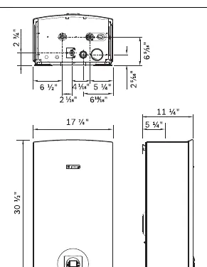
- Fig 6: Dimensions and clearance requirements
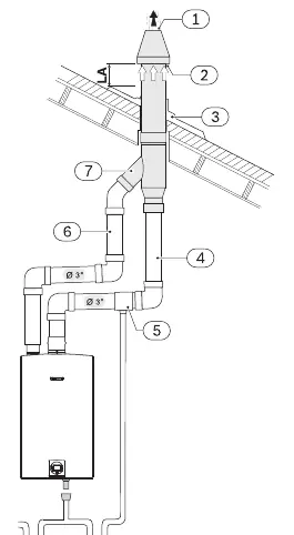
- Fig 9: Concentric vent kit example
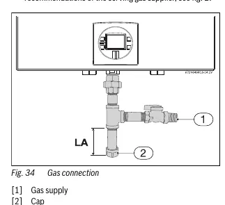
- Fig 34: Gas connection setup
- Fig 38: Filling condensate trap
Model compatibility
- Not for mobile homes or boats
- Requires 120VAC/60Hz power
- Requires qualified installer for gas/venting

Manual page author
Emily Carter
User documentation editor
Prepares concise manual descriptions and highlights the most useful setup, operation, and maintenance information for readers.