Home Appliances / Range Hoods
User Manual for Drija 13L Gas Water Heater
Quick guide for the Drija 13L gas water heater. Learn about installation requirements, safety precautions, operation instructions, maintenance, and troubleshooting error codes for model CLT13L.
Table of contents
Manual images
Click an image to enlargeQuick guide from the manual
This gas water heater is designed for domestic hot water supply. It requires professional installation by a registered gas installer. Key safety requirements include ensuring the unit is installed in a well-ventilated room with a floor drain, and that the flue pipe is correctly installed to exhaust waste gas outdoors. Always ensure the gas type matches the rating label (LPG 2800Pa) and that the power supply is 110V/50-60Hz.
Features
- Intelligent CPU control for performance management.
- Temperature setting range: 35°C to 65°C.
- Low water pressure start (0.02MPa).
- Memory function for previous settings.
- Multiple safety protections: anti-dry combustion, flame failure protection, overheat protection, and wind pressure protection.
Installation
Installation must be performed by a registered gas installer. The unit must be mounted vertically on a wall with at least 10mm clearance. Ensure the unit is grounded. The flue pipe must be installed to discharge exhaust outdoors. The gap between the pipe and the wall should be sealed with a 1° leaning angle to prevent water ingress.
Operation
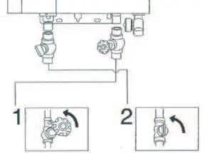
To operate the heater: 1. Ensure the gas type is correct, the gas supply system is leak-free, and the gas valve is turned on. 2. Turn on the power switch. 3. Open the water inlet or outlet valve; the heater will ignite automatically. 4. Use the adjusting knob at the bottom to control water flow and temperature. 5. After use, turn off the gas and water inlet valves. In freezing weather, drain the water from the heater.
Maintenance
Perform regular inspections. Before maintenance, close the main gas and water valves and unplug the power. Wipe the unit with a towel and kitchen cleanser (do not use benzene or thinner). Regularly remove and clean the filter at the water inlet using a toothbrush.
Troubleshooting and Error Codes
The unit features a display for error codes to assist in diagnostics:
- E0: Probe malfunction. Check connections of water flow transducer and temperature sensor.
- E1: Ignition failed. Check if the gas valve is open or if there is air in the gas pipe.
- E2: Sudden flame-out. Check flame probe connection.
- E3: Overheat protection. Water temperature exceeded 75°C.
- E4: Flue-pipe blocked or wind-pressure switch malfunction.
- E5: Solenoid-controlled valve malfunction.
- E6: Flame cannot die out immediately after closing water.
- E7: Fan motor malfunction.
- E9: Dry-combustion malfunction.
- EA: Water valve malfunction.
- EN: Time-out (normal operation limit).
Practical help
Common problems
Indicator light is not on
Check if the power is off and ensure the plug is inserted firmly.
No water flow / No operation
Ensure the gas valve and water valve are fully opened. Check for water supply suspension.
Water is not warm enough
Check if the gas valve is fully opened. Adjust the water flow volume or temperature setting.
E1 Error Code
Ignition failed. Ensure the main gas valve is open and there is no air in the gas pipe.
E3 Error Code
Overheat protection. The sensor detected water temperature over 75°C. Restart the heater.
Before use
- Ensure installation is performed by a registered gas installer.
- Verify the room is well-ventilated and has a floor drain.
- Confirm the gas type matches the rating label (LPG 2800Pa).
- Ensure the flue pipe is installed to exhaust waste gas outdoors.
- Check that the power supply is 110V/50-60Hz.
- Verify water inlet pressure is at least 0.02MPa.
Specs in practice
- Rated heating power
- 26kW
- Rated capacity
- 13L/min (at ΔT=20K)
- Working water pressure
- 0.015~0.8MPa
- Gas pressure
- LPG: 2800Pa
Images and diagrams
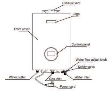
- The main components diagram identifies the exhaust vent, logo, front cover, control panel, water flow adjust knob, safety valve, and connection points for water and gas.
Model compatibility
- Requires LPG gas supply.
- Requires 110V/50-60Hz electrical connection.
- Minimum water pressure for ignition is 0.02MPa.

Manual page author
Michael Turner
Technical manual editor
Reviews PDF manuals for structure, safety notes, and practical product details so readers can find the right information quickly.